Coal decomposition method and equipment in cycle heating gas style

a cycle heating and gas-type technology, applied in the field of comprehensive utilization of coal substances, can solve the problems of high cost of raw materials, complex manufacturing process of each close-packed heating pipe, and low heat value, so as to ensure the purity of decomposed gas fundamentally, improve the safety of production process, and heat quickly

Active Publication Date: 2012-12-06
ZHU SHUCHENG
View PDF3 Cites 3 Cited by
  • Summary
  • Abstract
  • Description
  • Claims
  • Application Information

AI Technical Summary

Benefits of technology

[0003]To solve the above problems in prior arts, an object of the present invention is to provide a coal decomposition method and equipment in cycle heating gas style, which can avoid introducing impurity, ensure a pure decomposed gas and keep continuous heating without extrinsic heat source.
[0013]According to the present invention, since the decomposed gas is acted as heat transfer media, and make the coal decomposed gas produced in high temperature kiln body or inert gas enter the kiln body again through the heating pipe. The high temperature gas sufficiently contacts with the rolled pulverized coal so that the pulverized coal can adequately absorb heat and be heated up rapidly so as to be decomposed to more coal decomposed gas and high-value heat coal in the kiln body. A large proportion of the coal decomposed gas is collected, dedusted, separated and pressure liquefied. The high-value heat coal is output from the coal outlet, and a small amount of the coal decomposed gas or the separated inert gas enters the kiln body again after being heated to react with the undecomposed or newly-feeding coal. Thus, a circle of heating coal by the decomposed gas is finished. Most importantly, the decomposed gas is utilized as a media to contact and react with the coal so that no any new gas is introduced and thus ensure the purity of the decomposed gas fundamentally. In addition, using inert gas as heat transfer media can greatly improve the safety of production process, although a step of separating inert gas is added in the production process. The fuel in the fuel supply pipe used for heating the decomposed gas can also attained from a small part of the processed coal decomposed gas. Thus, the equipment of the invention can supply heat source by itself and is not necessary to add new heat source for the system. The coal decomposition method and equipment in cycle heating gas style of the present invention makes the decomposition and separation of the pulverized coal more fast and efficient so as to save and fully utilize energy and greatly increase the utilization rate and level of coal resources, thus it will produce a significant economic and social benefits for the entire society.

Problems solved by technology

However, the above-mentioned process is required to block pulverized coal or sift lamp coal, as a result, it increases the cost of raw material, or cause the produced gas without a high heat value, a big additional value, and a significant economy and social benefits.
However, in practical production process, on the one hand, the manufacturing process for each close-packed heating pipe is very complicated and there would be some problem of leakage and cross-channeling in this kind of sealing model, which may cause a potential safety problem.
In particularly, the problem of double rotation high temperature airtight between flame gas converged pipe of the flame gas heating pipe and coal decomposed gas collecting pipe also blocks a fast development of decomposition equipment.
In addition, the combustion chamber which has problems easily is set inside of the kiln body, so it is not convenient for inspection, overhaul and timely mastering combustion dynamic thereof, and thus increasing the quantity of security blind spots.

Method used


Image

  • Coal decomposition method and equipment in cycle heating gas style
  • Coal decomposition method and equipment in cycle heating gas style

Examples


embodiment 1

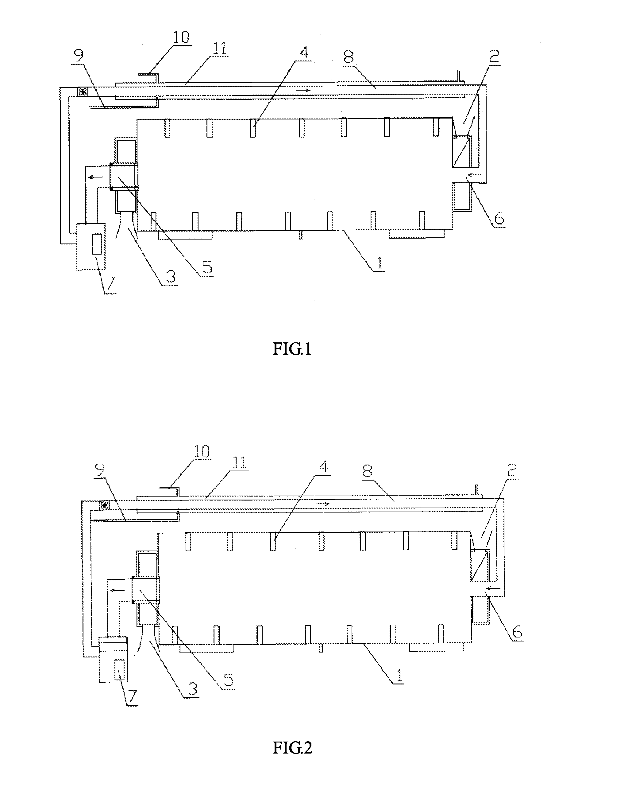
[0023]Referring to FIG. 1, an equipment for coal decomposition in cycle heating gas style comprises an airtight kiln body 1 with a coal inlet 2 and a coal outlet 3. The kiln body 1 is a rotary kiln. A facility 4 for impelling and decomposing coal is set in the kiln body 1, which can be in a style of lifter, spiral or other transversely-impelling type. A coal decomposed gas collecting pipe 5 is set in one end of the airtight kiln body 1, and a high temperature gas input pipe 6 is set in the other end of the airtight kiln body 1. A post-processing facility 7 is connected with the coal decomposed gas collecting pipe 5, which can be a device for producing gas, or a device for dedusting, purifying, desulfurization, pressure liquefying. The coal decomposed gas collecting pipe 5 communicates with the high temperature gas input pipe 6 through a circle pipe 8. The circle pipe 8 and / or the high temperature gas input pipe 6 comprises a heating device, which includes a fuel supply pipe 9, an ai...

embodiment 2

[0024]Referring to FIG. 2, an equipment for coal decomposition in cycle heating gas style comprises an airtight kiln body 1 with coal inlet 2 and coal outlet 3. The kiln body 1 is a rotary kiln. A facility 4 for impelling and decomposing coal is set in the kiln body 1, which can be in a style of lifter, spiral or other transversely-impelling type. A coal decomposed gas collecting pipe 5 is set in one end of the airtight kiln body 1, and a high temperature gas input pipe 6 is set in the other end of the airtight kiln body 1. A post-processing facility 7 is connected with the coal decomposed gas collecting pipe 5, which can be a device for producing gas, or a device for dedusting, purifying, desulfurization, pressure liquefying. The coal decomposed gas collecting pipe 5 communicates with the high temperature gas input pipe 6 through a circle pipe 8. The circle pipe 8 and / or the high temperature gas input pipe 6 comprises a heating device, which includes a fuel supply pipe 9, an air su...

embodiment 3

[0025]Referring to FIG. 3, an equipment for coal decomposition in cycle heating gas style comprises an airtight kiln body 1 with coal inlet 2 and coal outlet 3. The kiln body 1 is an up-draft kiln. A facility 4 for impelling and decomposing coal is set in the kiln body 1, which can be in a style of a large vertical spiral, grid vibration board or other vertically-impelling type. A coal decomposed gas collecting pipe 5 is set in one end of the airtight kiln body 1, and a high temperature gas input pipe 6 is set in the other end of the airtight kiln body 1. A post-processing facility 7 is connected with the coal decomposed gas collecting pipe 5, which can be a device for producing gas, or a device for dedusting, purifying, desulfurization, pressure liquefying. The coal decomposed gas collecting pipe 5 communicates with the high temperature gas input pipe 6 through a circle pipe 8. The circle pipe 8 and / or the high temperature gas input pipe 6 comprises a heating device, which includes...


PUM

PropertyMeasurementUnit
temperatureaaaaaaaaaa
heating valueaaaaaaaaaa

Abstract

The invention discloses a coal decomposition method and equipment in cycle heating gas style. The coal decomposition equipment can avoid introducing impurity, ensure a pure decomposed gas and keep continuous heating without extrinsic heat source, which includes an airtight kiln body with coal inlet and coal outlet; a facility for impelling and decomposing coal set in the kiln body; a coal decomposed gas collecting pipe set in one end of the airtight kiln body, and a high temperature gas input pipe set in the other end of the airtight kiln body; wherein the coal decomposed gas collecting pipe is connected with a post-processing facility and communicates with the high temperature gas input pipe through a circle pipe, and the circle pipe and / or the high temperature gas input pipe comprises a heating device.

Description

FIELD OF THE INVENTION[0001]The invention relates to comprehensive utilization of coal substance for saving energy and emission reduction, particularly to a cycle heating gas style decomposition method and equipment for coal.BACKGROUND OF THE INVENTION[0002]In convention technology, coal is used to produce coral gas, natural gas, or used to produce gas by coking at high temperature, medium temperature or low temperature. However, the above-mentioned process is required to block pulverized coal or sift lamp coal, as a result, it increases the cost of raw material, or cause the produced gas without a high heat value, a big additional value, and a significant economy and social benefits. The heating methods of furnace can be classified as external-heating style, internal heating style and hybrid-heating style. Specifically, the heating medium in external-heating furnace is not contact directly with raw materials and heat is conducted from furnace wall. The heating medium in the interna...

Claims


Application Information

Patent Timeline
Patent Type & Authority Applications(United States)
IPC IPC(8): C10L5/00
CPCC10B49/04C10B1/10C10B53/04C10B57/00C10B57/08C10B37/00C10B47/00
Inventor ZHU, SHUCHENG
Owner ZHU SHUCHENG
Why Eureka
Try Eureka