Crash structure for attachment to a front subframe for a motor vehicle

Inactive Publication Date: 2012-11-22
GM GLOBAL TECH OPERATIONS LLC
View PDF5 Cites 3 Cited by
  • Summary
  • Abstract
  • Description
  • Claims
  • Application Information

AI Technical Summary

Benefits of technology

[0007]A stiffened connection between the crash structure and the front subframe is achieved at least in the attachment area of the crash structure by the reinforcement of the crash structure in the attachment area on the front subframe. Through this reinforcement of the attachment area, any possible location changes of the front subframe because of lateral forces acting on the front subframe, as occur in driving operation of the motor vehicle, for example, are effectively counteracted. The front subframe is thus stabilized in its location, so that even upon the occurrence of lateral forces on the front subframe in operation of the motor vehicle, any possible location change in the area of the wishbone attachment points of the front subframe is decreased. The measure therefore has a stiffening effect on the entire front subframe, in particular on the wishbone attachment points of the front subframe.
[0027]According to still another embodiment, the front subframe, in the attachment area to the crash structure, has an outwardly open cavity, into which a connection element for threading into a passage opening of a wall of the front subframe can be introduced for fixing the crash structure on the front subframe. The assembly of front subframe and crash structure by means of the connection element is thus made easier, since a cavity is provided, in which the connection element can already be held in the direction in which the connection element can then be inserted into the passage opening without more extensive alignment, to produce a strong connection to the crash structure using the stiffening structure.

Problems solved by technology

Due to the sagging in the attachment area, a location change of the wishbone attachment points in the area of the front subframe occurs, which unfavorably influences the steering behavior of the motor vehicle.

Method used


Image

  • Crash structure for attachment to a front subframe for a motor vehicle
  • Crash structure for attachment to a front subframe for a motor vehicle
  • Crash structure for attachment to a front subframe for a motor vehicle

Examples


Embodiment Construction

[0031]The following detailed description is merely exemplary in nature and is not intended to limit the various embodiments or the application and uses thereof Furthermore, there is no intention to be bound by any theory presented in the preceding background or the following detailed description.

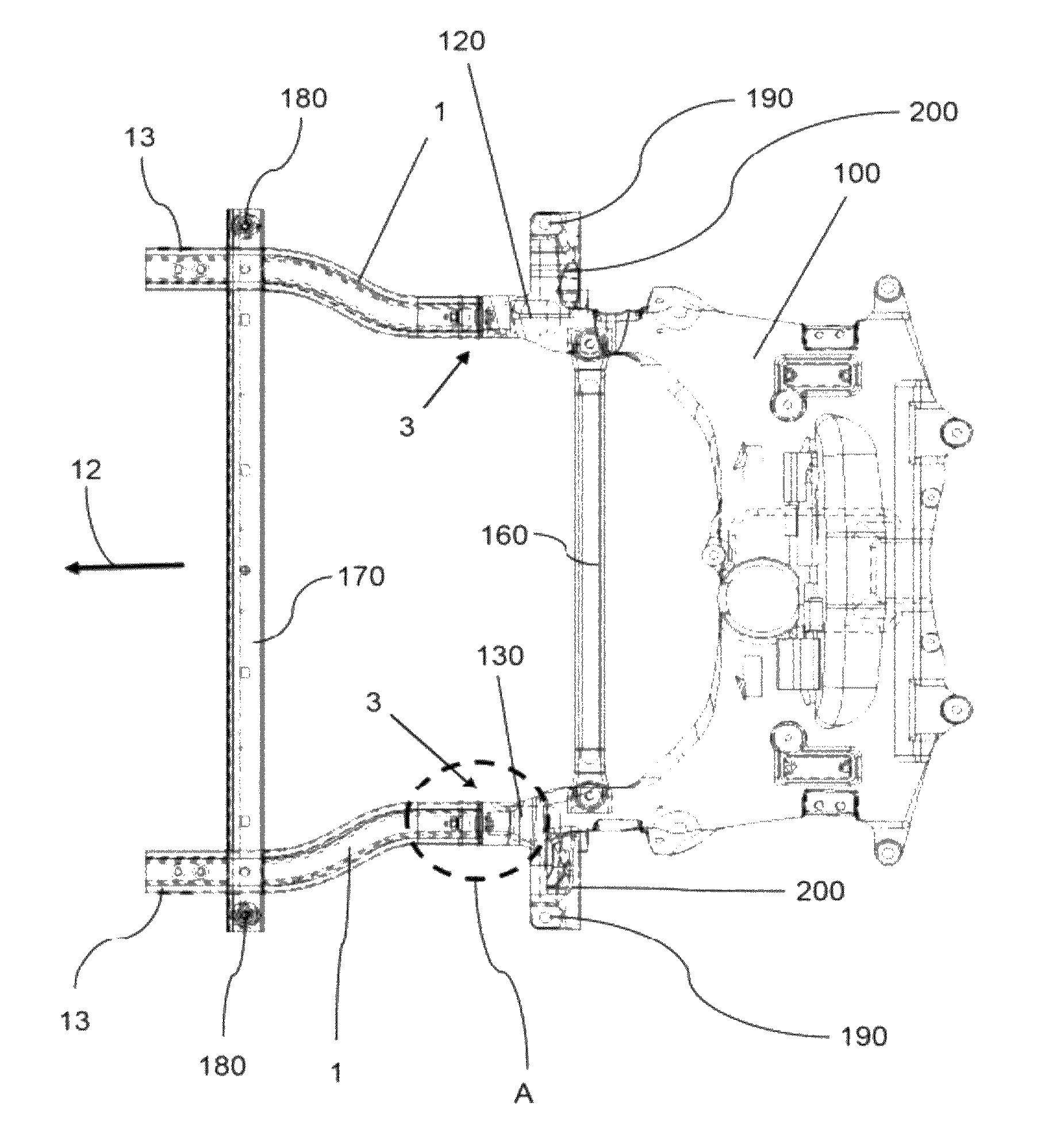
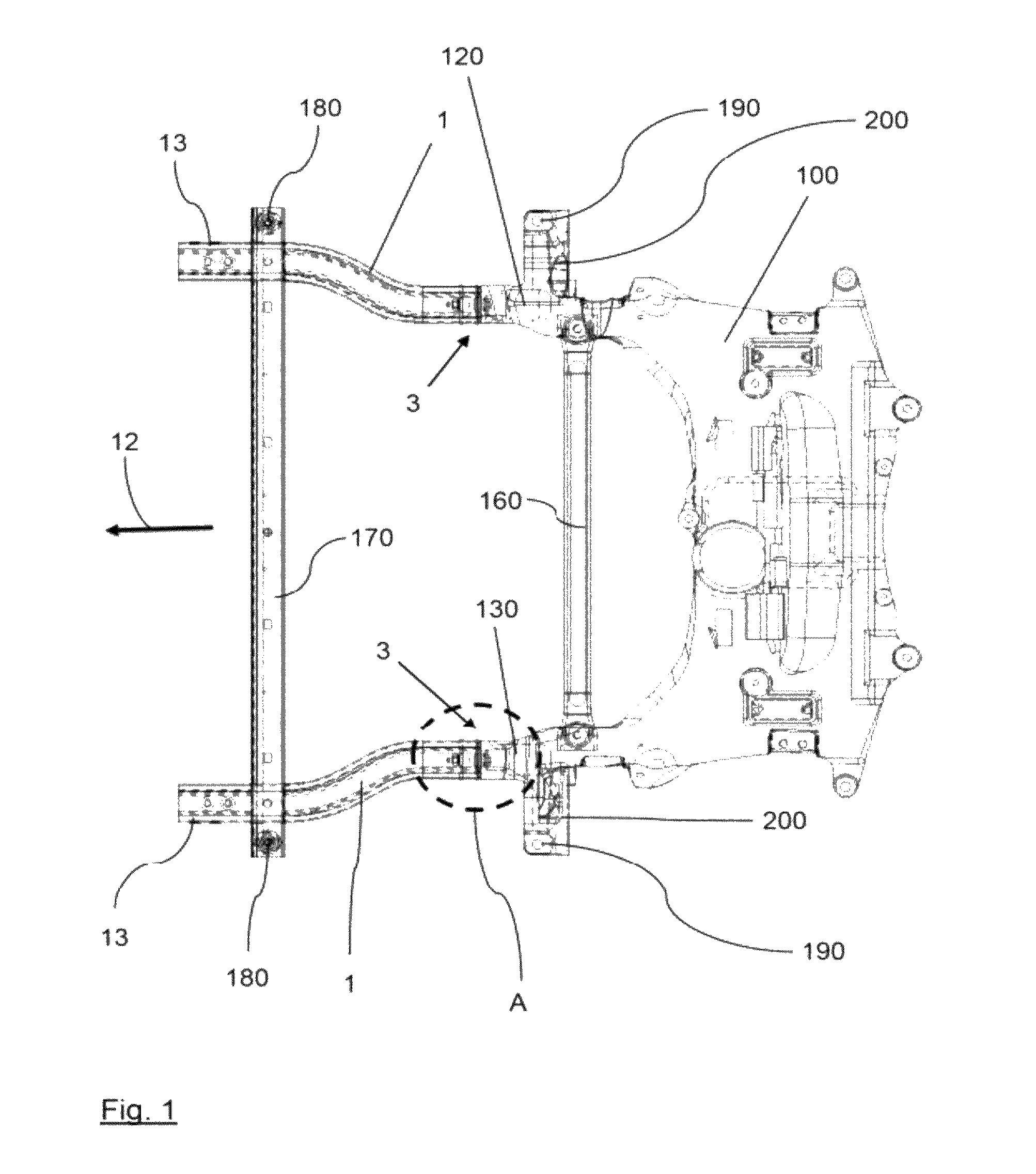
[0032]FIG. 1 shows an embodiment of a front subframe 100, in particular a front axle subframe. The front subframe 100 is preferably implemented as U-shaped, an embodiment of a crash structure 1 being fixed on the ends of each of the legs 120, 130 thereof.

[0033]For example, the front subframe 100 is used for the purpose of supporting the steering gear of the vehicle steering system, at least one stabilizer, at least one bearing for the engine mount, the wishbone, and the exhaust system of the motor vehicle. A tie bar 160 is preferably assigned or coupled to the front subframe 100, by which the two legs 120, 130 of the front subframe 100 are connected to one another. The tie bar 160 is prefera...


PUM


Abstract

A crash structure for attachment to a front subframe for a motor vehicle is provided. The crash structure includes an attachment area and a stiffening structure that reinforces the crash structure in the attachment area for the front subframe. The stiffening structure connects the crash structure to the front subframe in a friction-locked and / or formfitting manner.

Description

CROSS-REFERENCE TO RELATED APPLICATION[0001]This application claims priority to German Patent Application No. 10 2011 102 116.0, filed May 20, 2011, which is incorporated herein by reference in its entirety.TECHNICAL FIELD[0002]The technical field relates to a crash structure for attachment to a front subframe for a motor vehicle. Furthermore, the technical field relates to a front subframe, in particular a front axle subframe, for a motor vehicle.BACKGROUND[0003]Motor vehicles typically have a so-called front subframe or front axle subframe in the front end, which supports, inter alia, the steering gear, the stabilizer, the engine mount, the wishbone, and the exhaust system of the motor vehicle. A crash structure adjoins the front subframe in each case on the left longitudinal side and on the right longitudinal side of the front subframe, viewed in the vehicle direction, the crash structures also being designated as crash extensions. The crash structures are implemented like a long...

Claims


Application Information

Patent Timeline
IPC IPC(8): B62D25/08
CPCB62D27/065B62D21/155B62D21/152B62D27/06
Inventor UHLENBRUCH, LUTZEICHELHARD, OLIVER
Owner GM GLOBAL TECH OPERATIONS LLC
Why Eureka
Try Eureka