High powered light emitting diode lighting unit

Active Publication Date: 2012-11-15
LUMENPULSE GRP INC
View PDF3 Cites 36 Cited by
  • Summary
  • Abstract
  • Description
  • Claims
  • Application Information

AI Technical Summary

Benefits of technology

[0010]Another object of the present invention is to provide an improved heat transfer element, which further improves the conduction of heat, generated by the LEDs and through and out of the LED lighting unit so that the LED lighting unit operates at a cooler temperature and thereby reduces the possibility or likelihood that the generated heat from the LEDS will adversely affect the power supply and / or the associated electronic circuitry.
[0011]A further object of the present invention is to provide a centrally located chimney, formed in at least one of a rear surface of the power supply housing, and a front surface of the LED array housing, which directly communicates with the air flowing into and through the heat transfer element and thereby facilitates improved convection airflow into and out of the LED lighting unit, which provides a more efficient cooling of the LED lighting unit and thereby increases the durability of the LED lighting unit incorporating the same.
[0012]Yet another object of the present invention is to provide the chimney with a reduced area throat section as well as a suitable cross sectional airflow area which avoids restricting pass natural convention flow of air into and through the chimney and thereby improves the overall cooling of the LED lighting unit and, in turn, the LEDs and the internal components accommodated within the LED lighting unit.
[0019]In another aspect, at least one embodiment described herein provides a process for dissipating heat from a solid-state lighting unit comprising a solid-state array housing fixedly attached to and spaced apart from a power supply housing. The process includes transferring thermal energy from a rear surface of the solid-state array housing to heat air in a space between the solid-state housing and the power supply housing. The heated air is channeled into an open end of a chimney defined in the power supply housing and including a lumen having a first open end facing the rear surface of the solid-state array housing. The channeled air creates airflow through the chimney that reduces a pressure in the space between the solid-state housing and the power supply housing. Ambient air is drawn laterally into the space between the solid-state housing and the power supply housing in response to the reduced pressure.
[0020]In another aspect, at least one embodiment described herein provides a solid-state lighting unit including a solid-state array housing defining an internal compartment and a solid-state array module. The solid-state array module includes an array of solid-state lighting elements, a solid-state lighting element control circuit and a printed circuit board. The solid-state array module is accommodated within the internal compartment of the solid-state array housing having a rear surface that includes a heat transfer element. The lighting unit further includes a power supply housing accommodating a power supply. The power supply housing has a front surface opposing the rear surface of the solid-state array housing. The rear surface of the solid-state array housing is fixedly disposed in a spaced apart relationship with respect to the front surface of the power supply housing, such that an airflow space is defined therebetween so that, during operation of the solid-state lighting unit, air flows into the airflow space and to facilitate removing heat from the solid-state lighting elements.
[0021]In yet another aspect, at least one embodiment described herein provides solid-state lighting unit including means for transferring thermal energy from a rear surface of the solid-state array housing to heat air in a space between the solid-state housing and the power supply housing. Also provided are means for channeling the heated air into an open end of a chimney defined in the power supply housing. The chimney includes a lumen having a first open end facing the rear surface of the solid-state array housing. The channeled air creates airflow through the chimney that reduces a pressure in the space between the solid-state housing and the power supply housing. The lighting unit also includes means for drawing ambient air laterally into the space between the solid-state housing and the power supply housing in response to the reduced pressure.

Problems solved by technology

A recurring problem with such higher powered LED array lighting units, however, is the heat generated by such high powered LED arrays, which often adversely effects the power and control circuitry of the lighting units and the junction temperatures of the LEDs, resulting in shortened use life and an increased failure rate of one or more of the power and control circuitry and the LEDs.
This problem is compounded by the heat generated by, for example, the LED array power circuitry and is particularly compounded by the desire for LED lighting units that are compact and of esthetically pleasing appearance as such considerations often result in units having poor heat transfer and dissipation characteristics with consequently high interior temperatures and “hot spots” or “hot pockets.”

Method used


Image

  • High powered light emitting diode lighting unit
  • High powered light emitting diode lighting unit
  • High powered light emitting diode lighting unit

Examples


Embodiment Construction

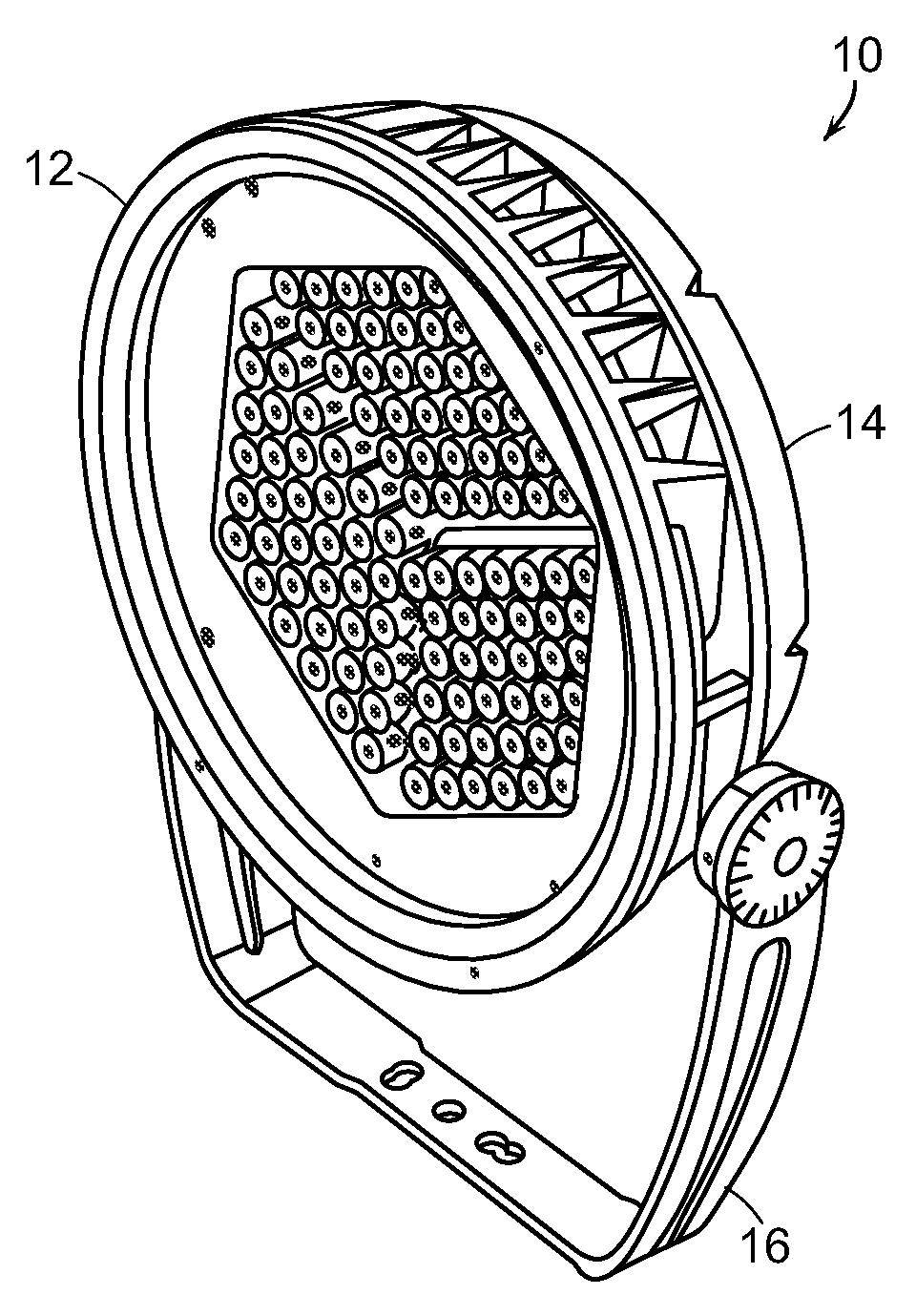
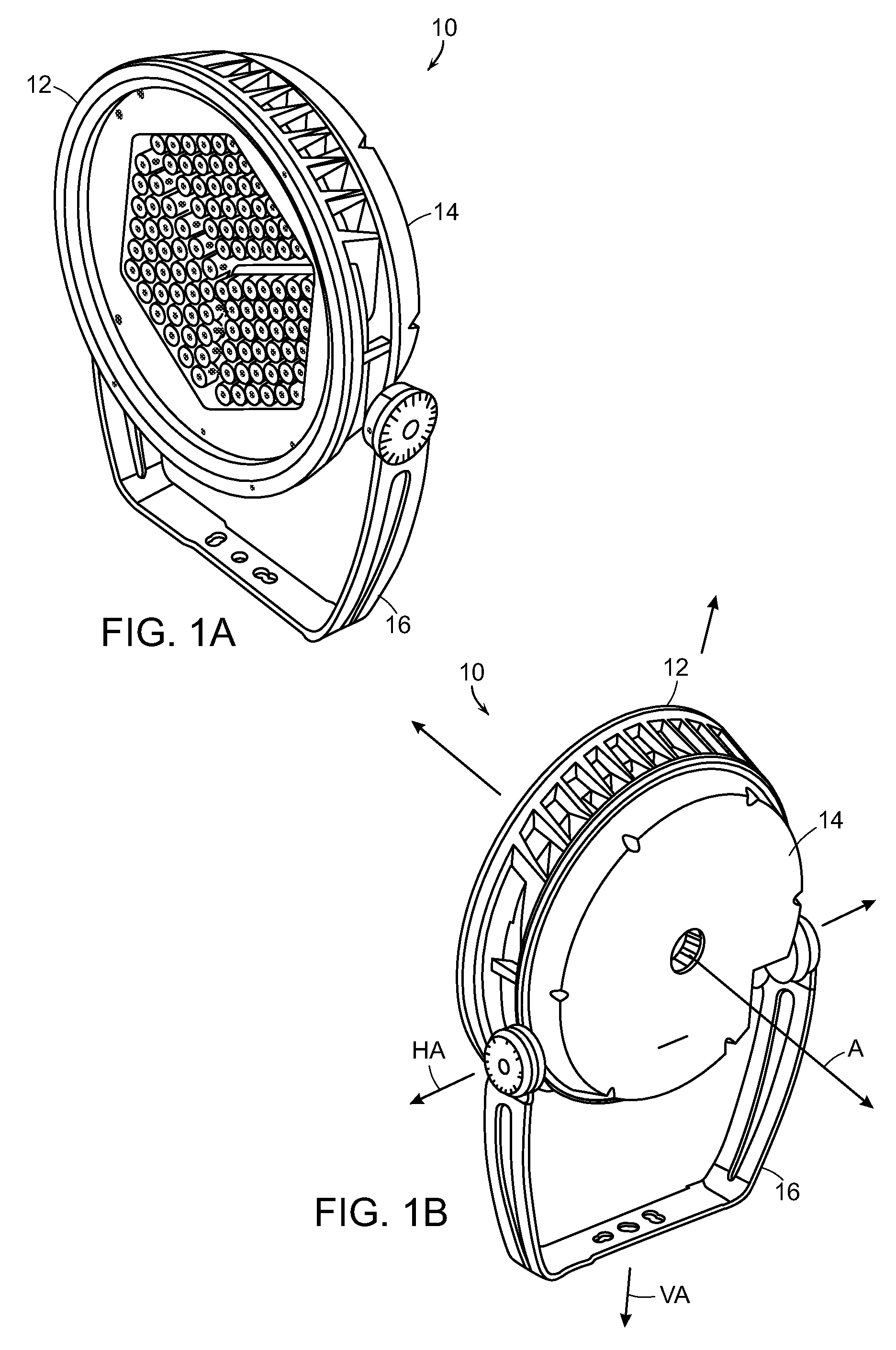
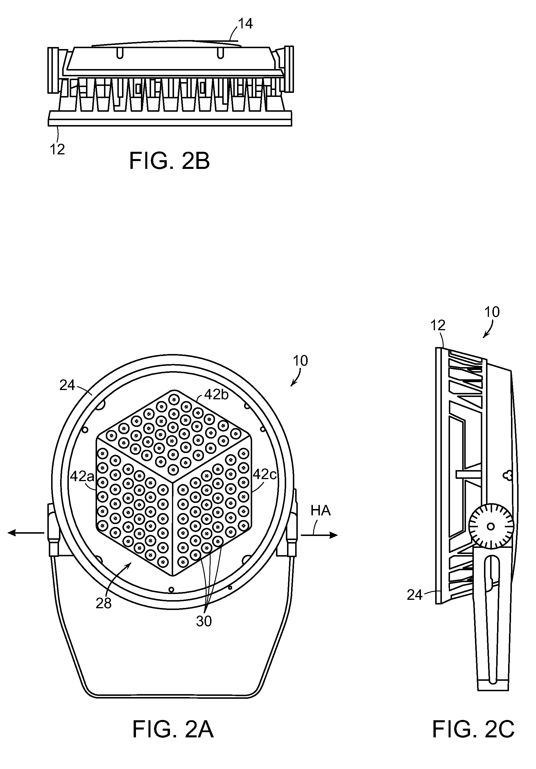
[0042]In the following detailed description of the preferred embodiments, reference is made to accompanying drawings, which form a part thereof, and within which are shown by way of illustration, specific embodiments, by which the invention may be practiced. It is to be understood that other embodiments may be utilized and structural changes may be made without departing from the scope of the invention.

[0043]The particulars shown herein are by way of example and for purposes of illustrative discussion of the embodiments of the present invention only and are presented in the case of providing what is believed to be the most useful and readily understood description of the principles and conceptual aspects of the present invention. In this regard, no attempt is made to show structural details of the present invention in more detail than is necessary for the fundamental understanding of the present invention, the description taken with the drawings making apparent to those skilled in t...


PUM

PropertyMeasurementUnit
Pressureaaaaaaaaaa
Electrical conductoraaaaaaaaaa
Transparencyaaaaaaaaaa

Abstract

A light emitting diode (LED) lighting unit including power supply housing accommodating a power supply and an LED array housing defining an internal compartment and a lens sealing the internal compartment. An LED array and an LED control circuit are mounted on a printed circuit board, which is accommodated within the compartment. The rear surface of the LED array housing includes a heat transfer element. At least one of the LED array and power supply housings has a chimney extending therethrough from a front to rear surface. The rear surface of the LED array housing is spaced from the front surface of the power supply housing to define and airflow space therebetween. During operation of the LED lighting unit, air flows into the airflow space and toward a central axis of the LED lighting unit before flowing out through the chimney to facilitate removing heat from the LED lighting unit.

Description

RELATED APPLICATIONS[0001]This application claims the benefit of U.S. Provisional Application No. 61 / 485,904, filed May 13, 2011. The entire teachings of the above application are incorporated herein by reference.BACKGROUND[0002]1. Technical Field[0003]This application relates generally to the field of lighting. More particularly, this application relates to the technology of high power light emitting diode (LED) lighting units, e.g., providing approximately 9,000 lumens of total illumination at 150 watts power dissipation, and, in particular, to a higher power LED lighting unit for indoor and outdoor lighting functions, such as architectural lighting, having a dynamically programmable single or multiple color array of high power LEDs and improved heat dissipation characteristics.[0004]2. Background Information[0005]Developments in LED technology have resulted in the development of “high powered” LEDs having light outputs on the order of, for example, 70 to 80 lumens per watt, so th...

Claims


Application Information

Patent Timeline
IPC IPC(8): F21L4/02F21V21/14F21V29/02F21V29/00F21V21/00F21V29/15
CPCF21V29/004F21V21/30F21Y2101/02F21Y2105/001F21V5/007Y10T29/49002F21V29/15F21V29/507F21V29/74F21V29/83F21V29/89F21V23/023F21Y2105/10F21Y2115/10F21V29/80
Inventor HAMEL, YVANCAMPBELL, GREGORY
Owner LUMENPULSE GRP INC
Why Eureka
Try Eureka