Flow Control Line Management Apparatus
a flow control and line management technology, applied in the direction of instruments, medical devices, drugs and medications, etc., can solve the problem that the gravity feeding of materials from the primary and secondary bags may occur at a higher than desired flow ra
- Summary
- Abstract
- Description
- Claims
- Application Information
AI Technical Summary
Benefits of technology
Problems solved by technology
Method used
Image
Examples
first embodiment
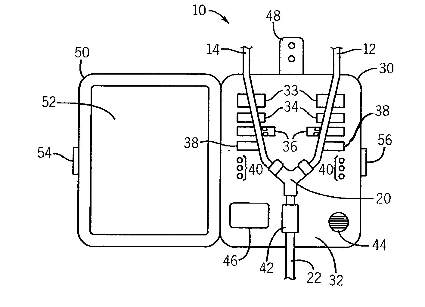
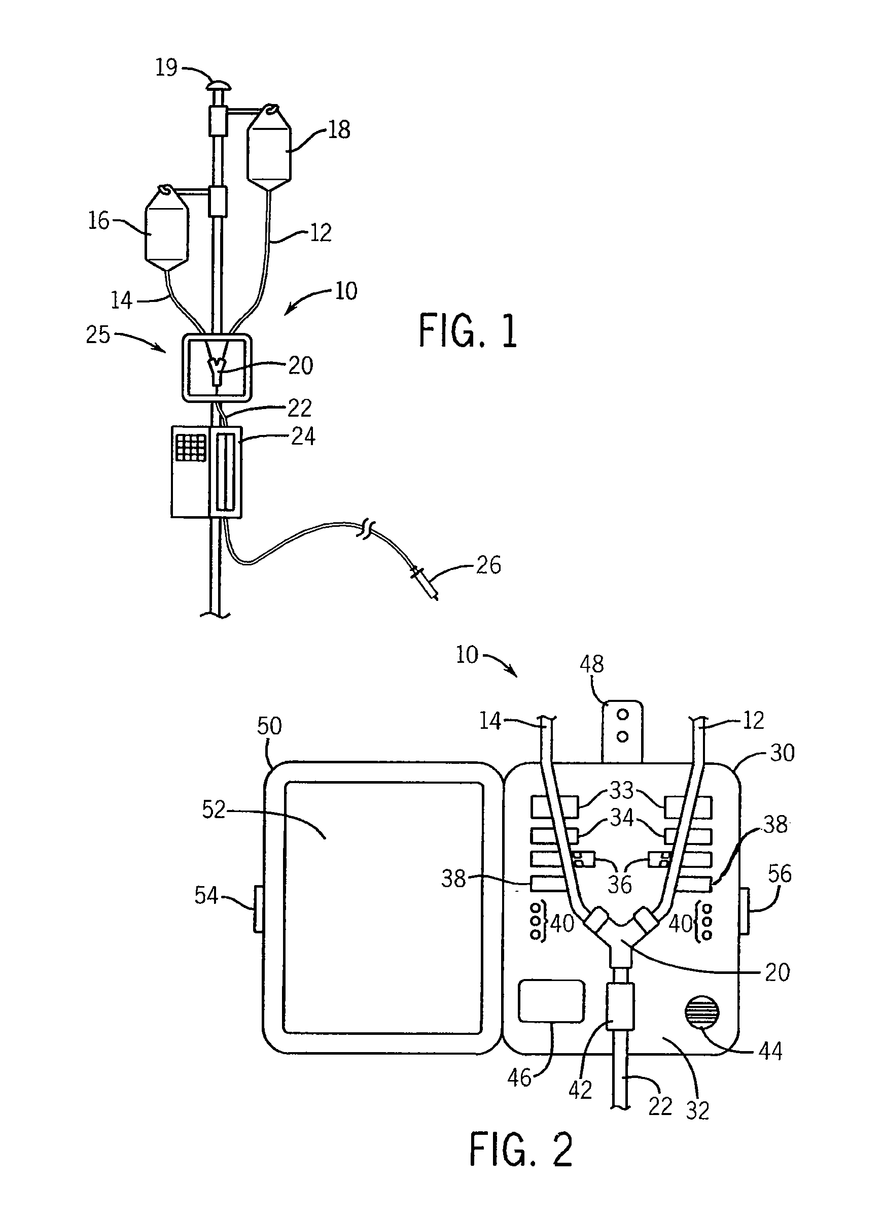
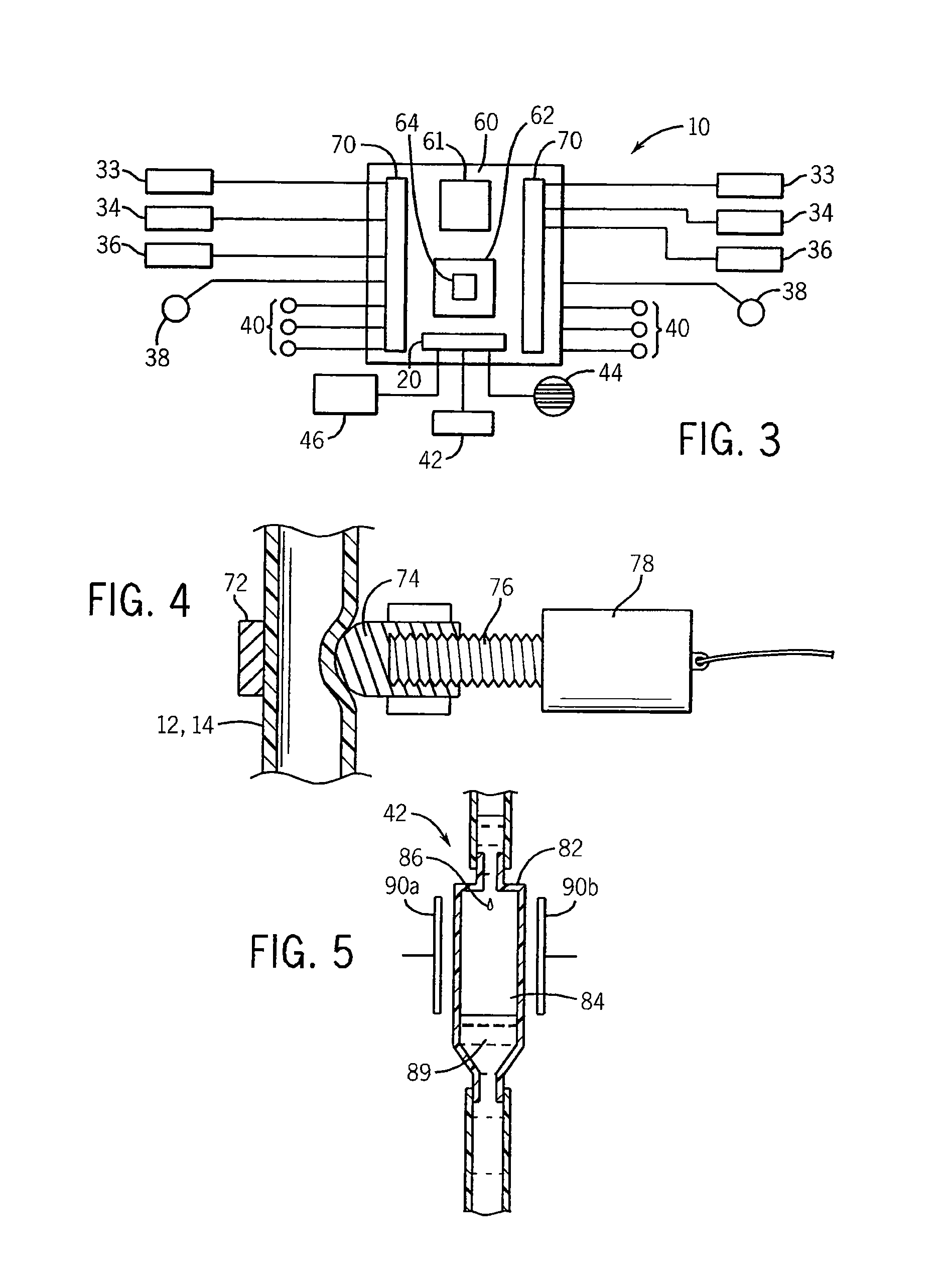
[0057]Referring now to FIG. 5, in the invention, the flow rate sensor 42 may provide for a generally cylindrical housing 82 receiving a flexible tube of the IV line 12 or 14 and having a diameter substantially larger than the diameter of the tube of IV lines 12 and 14. A connection between the tube and the housing 82 provides an orifice opening into an air space 84, the orifice forming liquid from the IV bag 16 or 18 into drops 86 that may fall through the air space 84 into a pool 89 at the bottom of the cylindrical housing 82. The pool 89 may communicate with a second tube providing a drain therefrom and a continuation of the IV line as outlet line 22.
[0058]When the flow rate sensor 42 (formed with the piggyback tubing assembly 25) is placed within a socket in the front face 32 of the housing 30, it will be flanked by first and second plates 90a and 90b positioned across a diameter of the cylindrical housing 82 and accordingly across the air space 84. Drops 86 passing through the a...
second embodiment
[0059]Referring now to FIGS. 6a and 6b, in a second embodiment the flow rate sensor 42 may also provide for a cylindrical housing 100. In this case the cylindrical housing 100 holds suspended therein a free spinning turbine 102 having a rotational axis 104 generally along the direction of flow and along the axis of the cylindrical housing. The cylindrical housing 100 may be attached at its upper and lower ends to outlet line 22 leading from the Y-connector 20 to be placed in series with the outlet line 22. Generally, the turbine 102 provides for one or more canted blades 106 having a known pitch to cause a predetermined rotational rate of the turbine 102 with flow of the liquid within the cylindrical housing 100 along axis 104.
[0060]Plates 90a and 90b may flank the cylindrical housing 100 when the flow rate sensor 42 is placed within the socket in the front face 32 of the housing 30 as described above with respect to the embodiment of FIG. 5. One or more blades 106 of the turbine 10...
PUM
 Abstract
Description
Claims
Application Information
 - R&D
- Intellectual Property
- Life Sciences
- Materials
- Tech Scout
- Unparalleled Data Quality
- Higher Quality Content
- 60% Fewer Hallucinations
Browse by: Latest US Patents, China's latest patents, Technical Efficacy Thesaurus, Application Domain, Technology Topic, Popular Technical Reports.
© 2025 PatSnap. All rights reserved.Legal|Privacy policy|Modern Slavery Act Transparency Statement|Sitemap|About US| Contact US: help@patsnap.com


