
Multiple measurement techniques including focused beam scatterometry for characterization of samples

Active Publication Date: 2012-10-25
ONTO INNOVATION INC
View PDF8 Cites 25 Cited by
  • Summary
  • Abstract
  • Description
  • Claims
  • Application Information

AI Technical Summary

Problems solved by technology

As sample structure dimensions become smaller than or comparable to the light wavelength, simple imaging such as microscopy is not possible, and the measurements require analysis of the intensity and / or the polarization state of the light scattered off the sample structure.

Method used


Image

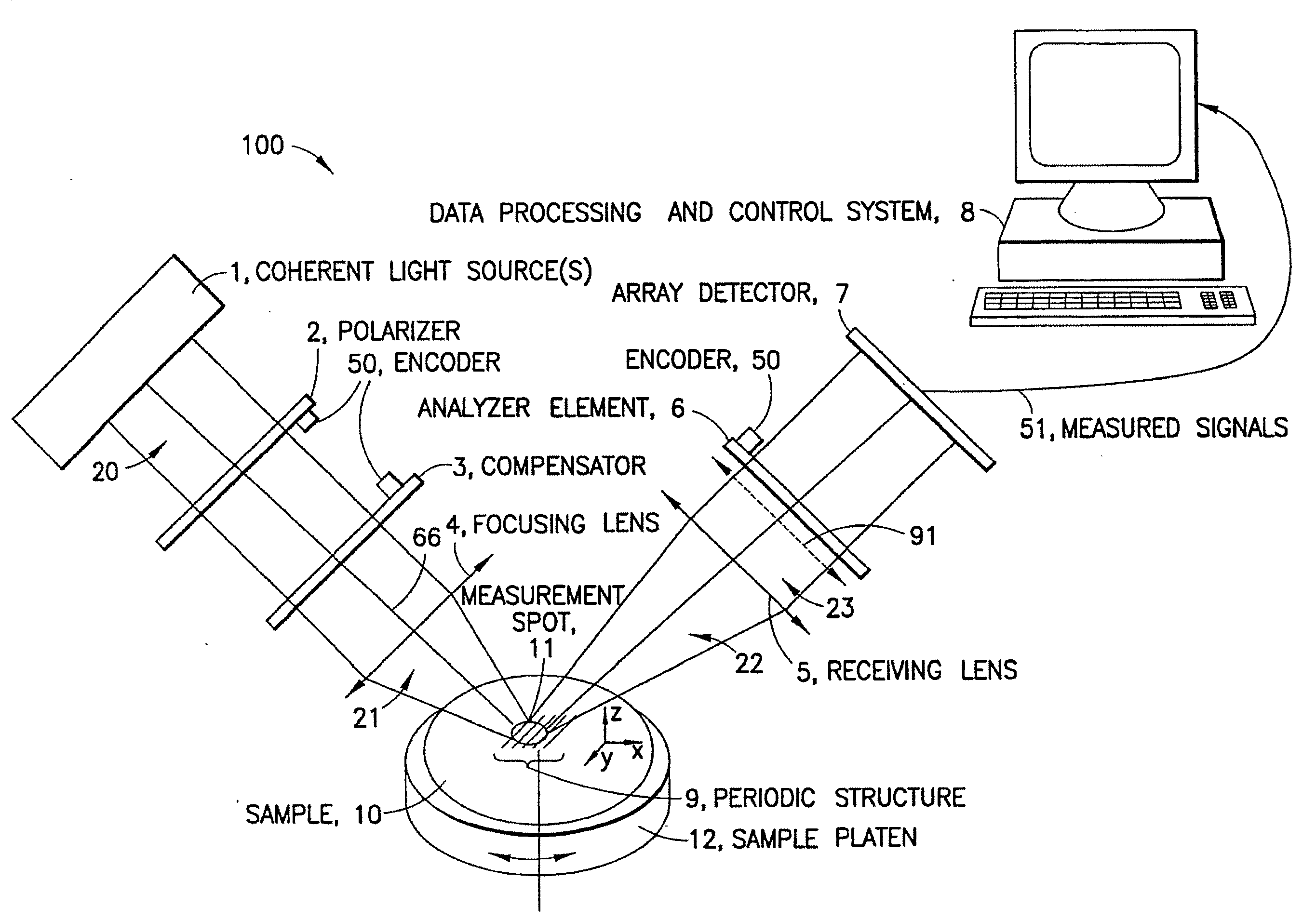
  • Multiple measurement techniques including focused beam scatterometry for characterization of samples
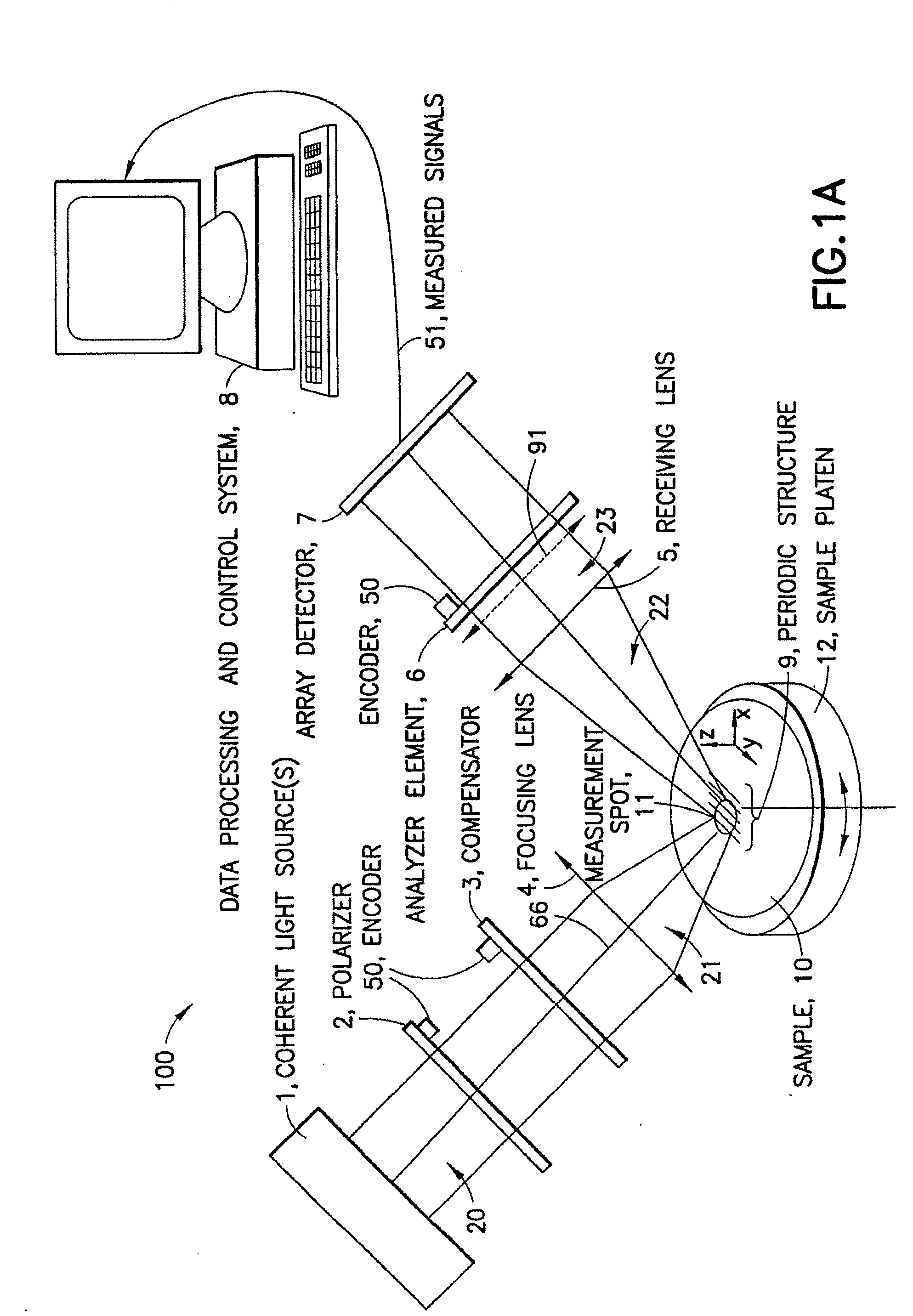
  • Multiple measurement techniques including focused beam scatterometry for characterization of samples
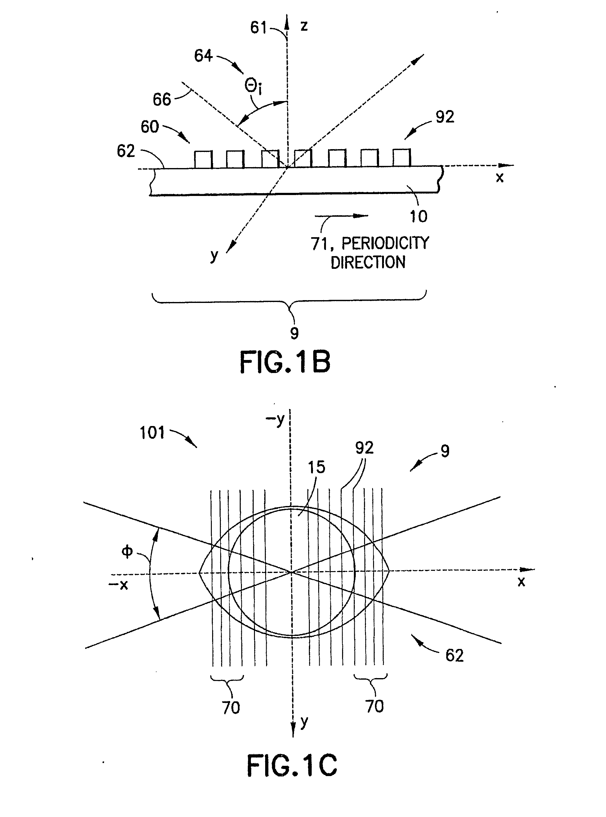
  • Multiple measurement techniques including focused beam scatterometry for characterization of samples

Examples


Embodiment Construction

[0014]Wherever possible, the standard definitions of words used in this specification have been adopted. However, to minimize misunderstanding the following words are defined with added particularity: “characteristic”, “parameter”, “model”, “sample”, and “structure”. It is understood that the preceding words have generally understood meanings and to the extent possible, those meanings have been followed. The additional definitions found below are for clarification purposes only.

[0015]Sample—a sample may be any thing having one or more structures or materials deposited or formed thereon. As used herein, the terms “sample”, “substrate”, and “wafer” may be used interchangeably.

[0016]Structure—a structure is a thing on the sample or part of the sample that is being measured. Note that the term “structure” may be used interchangeably at times to denote an item such as, e.g. a grating, line or a layer that is formed on the sample. Further, it should be recalled that samples are typically ...


PUM


Abstract

A system for monitoring thin-film fabrication processes is herein disclosed. Diffraction of incident light is measured and the results are compared to a predictive model based on at least one idealized or nominal structure. The model and / or the measurement of diffracted incident light may be modified using the output of one or more additional metrology systems.

Description

CROSS REFERENCE TO RELATED APPLICATION[0001]This application is a continuation of International Patent Application No. PCT / US2007 / 016842 filed Jul. 27, 2007.TECHNICAL FIELD[0002]This invention relates generally to measurement of samples and, more specifically, relates to focused beam scatterometry and other metrology measurements of samples.BACKGROUND OF THE INVENTION[0003]With the increasing integration density and operating frequencies of microelectronic devices, manufacturing processes for these devices require the ability to measure dimensions of submicron structures that make up the devices and thickness of the thin films deposited on, around, or under the structures. These measurements are performed during the numerous lithography, etching, and thin-film deposition steps of the manufacturing process. New transistor generations are built of non-planar structures defined during processing of multilayered films, and these generations require metrology measurements beyond just mea...

Claims


Application Information

Patent Timeline
IPC IPC(8): G01N21/55
CPCG01B11/02G01B11/0625G01N2021/213G01B11/24G01B2210/56G01N21/211G01B11/0641G01N21/95607G01N21/4788
Inventor WOLF, ROBERT GREGORYKOTELYANSKII, MICHAEL J.
Owner ONTO INNOVATION INC
Learn More