
Container treatment machine and method of treating containers

a container and treatment machine technology, applied in the direction of charge manipulation, furnaces, cleaning using liquids, etc., can solve the problems of high closing force of the gripper, and often occurring oscillating motion of the preform, so as to reduce the change-over time, prevent damage, and be easily placed in a clean room

Active Publication Date: 2012-10-18
KRONES AG
View PDF3 Cites 26 Cited by
  • Summary
  • Abstract
  • Description
  • Claims
  • Application Information

AI Technical Summary

Benefits of technology

The patent text describes a container treatment machine with grippers that can be better adapted to different operational problems and methods. The grippers can be individually and separately actuated, allowing for flexible and efficient operation. The machine can perform container treatment methods with higher quality results. The grippers can be used in various transport sections of the machine and can be controlled automatically or with minimal human intervention. The grippers can be used in different types of preforms and containers, and can even be used in meandering or buffer systems. The grippers can be uncontrolled or controlled, and can be overlaid over the normal opening movement of the machine. Overall, the patent text provides a solution for improving the performance and quality of container treatment machines.

Problems solved by technology

Such uncontrolled mechanical grippers generate high closing forces in the gripping position which can generate, for example at heated preforms, deformations or, in the acceptance or delivery of containers, undesired frictional forces.
In procedures in container treatment plants or in container treatment machines, however, different problems arise in practice which result, among other things, from the functional principle of the grippers, wear, work tolerances and a susceptibility of the treated preforms or containers to mechanical loads generated by the grippers.
This drawing off, however, results in a shaking displacement of the preform in the blow mold.
Nevertheless, an oscillating motion of the preform often occurs due to which the preform is no longer positioned sufficiently exactly relative to the blow mold halves.
This disadvantageous effect is even amplified by the small difference in the diameter in the holding region of the blow mold compared to the diameter of the preform.
Due to a displacement of the preform in the blow mold in such a disharmonic delivery from the gripper, the stretching rod inserted into the blow mold does no longer hit the center of the preform's bottom dome as actually predetermined.
This results in an unstable container bottom as the wall thickness is thicker on one side than on the side of the bottle bottom where the stretching rod contacted the preform eccentrically.
However, it regularly occurs that the maintenance intervals for precise recalibration are not respected.
Such recalibration optionally also becomes necessary when the machine performance is increased or reduced because this, too, can result in a displacement of the deposit point adjusted during the installation.
In case of a change of types, at least the contact elements must be exchanged to date, which is very time-consuming.
Furthermore, differently dimensioned preform or container types require different gripping forces in the acceptance, delivery and during transport, while conventional grippers do not permit a force control or path control of the gripper claws to date.
In a blow molding station of a stretch-blow molding machine, the stretching rod drive sometimes fails, so that the stretching rod is not properly retracted from the blow mold after a blow-molding process when a new preform reaches the empty blow mold.
Since conventional grippers operate with a compulsory and invariable motion sequence, one cannot consider the dangerous situation in case of a failure of the stretching rod drive, so that a collision between the preform held by the gripper and the stretching rod occurs, resulting in a malfunction.
This also applies to other incorrect positions of parts of a blow molding station caused by a failure, such as the blow mouth, the mold locking, or the like.
If, however, the container treatment machine is operated at a lower machine performance, for example below 1000 containers / h, the operational load in the train of gears becomes lower, so that the adjusted alignment is then possibly no longer compensated and preform delivery problems occur if no corresponding previous change of the misalignment has been performed, which is time-consuming.
To date, the grippers are not able to compensate this disadvantage without prior calibration works.
In case of a change of the preform type, therefore the gripping force would have to be correspondingly adapted, which is time-consuming and in many cases not possible as the gripping movement cannot be force-controlled and / or path-controlled.
If now no preform is delivered by the holding arbor due to a malfunction, or if a defective preform has been discharged before, or if the machine is operated in the mode “only use every second pitch”, with conventional grippers, a collision between the gripper claws of an uncontrolled gripper and the holding arbor cannot be avoided because no preform is located in-between.
This can lead to damages at the holding arbor and / or the gripper claws.
A conventional gripper holds the preform or container during the complete cycle in an exactly predetermined position relative to the inlet nozzle which makes it difficult to intensify the treatment or to also properly treat the contact region between the mouth rim and the web and / or gripper claw contact regions.
Due to their curved path controls, conventional grippers often cause problems in the operation in a clean room environment, for example at transfer arms of transfer starwheels, as by wear and the required lubrication of the curved path controls, contamination of the clean room atmosphere can be hardly avoided, or as it is difficult to install clean room seal, which are technically extremely complicated.
In practice, however, problems can occur if a container handed over by a gripper of a transfer starwheel is not immediately properly accelerated and carried off by the air jets.
Then, a jam of containers that can lead to container damages and requires the operator's intervention can occur.

Method used


Image

  • Container treatment machine and method of treating containers
  • Container treatment machine and method of treating containers
  • Container treatment machine and method of treating containers

Examples


Embodiment Construction

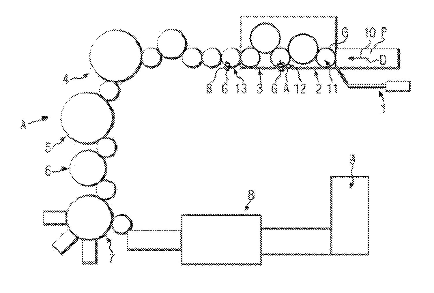
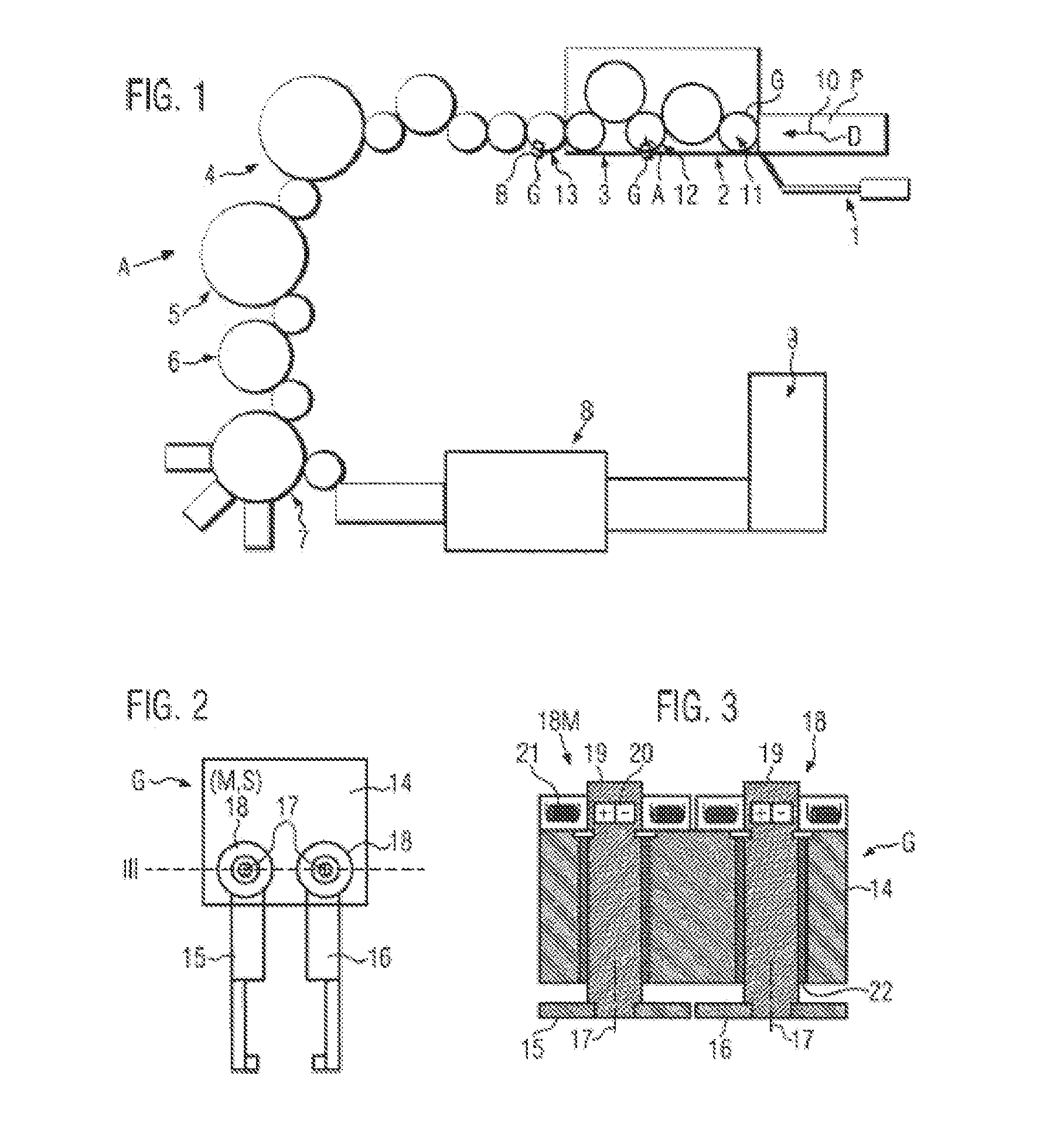
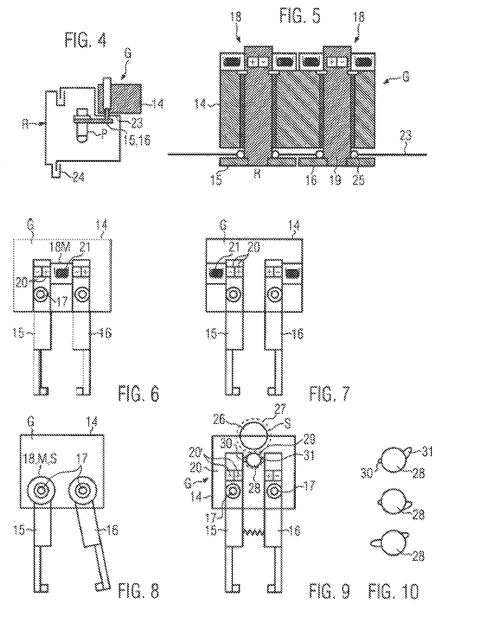
[0079]A container treatment plant A represented in FIG. 1 as a non-restricting example comprises a transport section 10 for preforms P as a part of a heating module 1 in which the preforms P are transported, for example, at holding arbors D or internal grippers to a further transport section 11 defined by a transfer starwheel, for example in an intermediate module 2 in which (optionally) the preforms P are subjected to a preferential heating process (see FIGS. 29, 30). In the process, they are contacted with temperature-control contact elements acting as gripper claws to apply a temperature profile varying e.g. in the circumferential direction. This is followed by a blow module as a further container treatment machine 3 in which a transfer starwheel 12 transfers the temperature-controlled preforms into split blow molds with transfer arms A and grippers G under pitch distortion compensation. The blow-molded or stretch-blow molded containers B are then transported via transfer starwhe...


PUM

PropertyMeasurementUnit
lengthaaaaaaaaaa
lengthaaaaaaaaaa
swivel anglesaaaaaaaaaa

Abstract

A container treatment machine with at least one gripper, which can be compulsorily transported along a predetermined transport section for handling a preform or container during transport and / or acceptance and / or delivery, and including, at a holder retaining at least two gripper claws, at least one controllable electric or magnetic drive for the gripper claws, where the gripper claws can be moved relative to each other in opening and closing directions and at least between defined gripping and release positions, and where each gripper claw can be individually separately actuated by the drive in the opening and / or closing direction relative to another gripper claw of the gripper. Alternately, both gripper claws can be actuated together in the same direction.

Description

CROSS-REFERENCE TO RELATED APPLICATION[0001]The present application claims the benefit of priority of German Application No. 102011007280.2, filed Apr. 13, 2011. The entire text of the priority application is incorporated herein by reference in its entirety.FIELD OF THE DISCLOSURE[0002]The disclosure relates to a container treatment machine with a holder having gripper claws, and a corresponding method.BACKGROUND[0003]U.S. Pat. No. 5,253,911 A discloses a controlled gripper wherein at its holder of two gripper claws, an electric servomotor is mounted which symmetrically swivels, via a rotary cam, the gripper claws in the closing direction against the force of an opening spring. The gripper claws not only symmetrically move in opposite directions, but compulsorily assume exactly predetermined relative positions at the holder in the gripping position and in the release position. These relative positions very precisely determine the position of the gripped object and the gripping and d...

Claims


Application Information

Patent Timeline
Patent Type & Authority Applications(United States)
IPC IPC(8): B65G47/90A61L2/16B65G47/86B08B9/08B29C49/78B65G47/92
CPCB29C49/4205B29C49/421B65G29/00B29C49/78B29C49/4236B29C49/4252B65G47/847B29C49/42069B29C49/42073B29C49/42075B29C49/42095B29C49/42099B29C49/42362B29C49/42418B29C2049/7878
Inventor WINZINGER, FRANK
Owner KRONES AG
Learn More