
System and method for plasma monitoring using microwaves

a plasma monitoring and microwave technology, applied in the field of plasma processing, can solve problems such as damage to components, dielectric windows, and power dissipation of hardware components by applied power

Active Publication Date: 2012-10-11
VARIAN SEMICON EQUIP ASSOC INC
View PDF11 Cites 104 Cited by
  • Summary
  • Abstract
  • Description
  • Claims
  • Application Information

AI Technical Summary

Benefits of technology

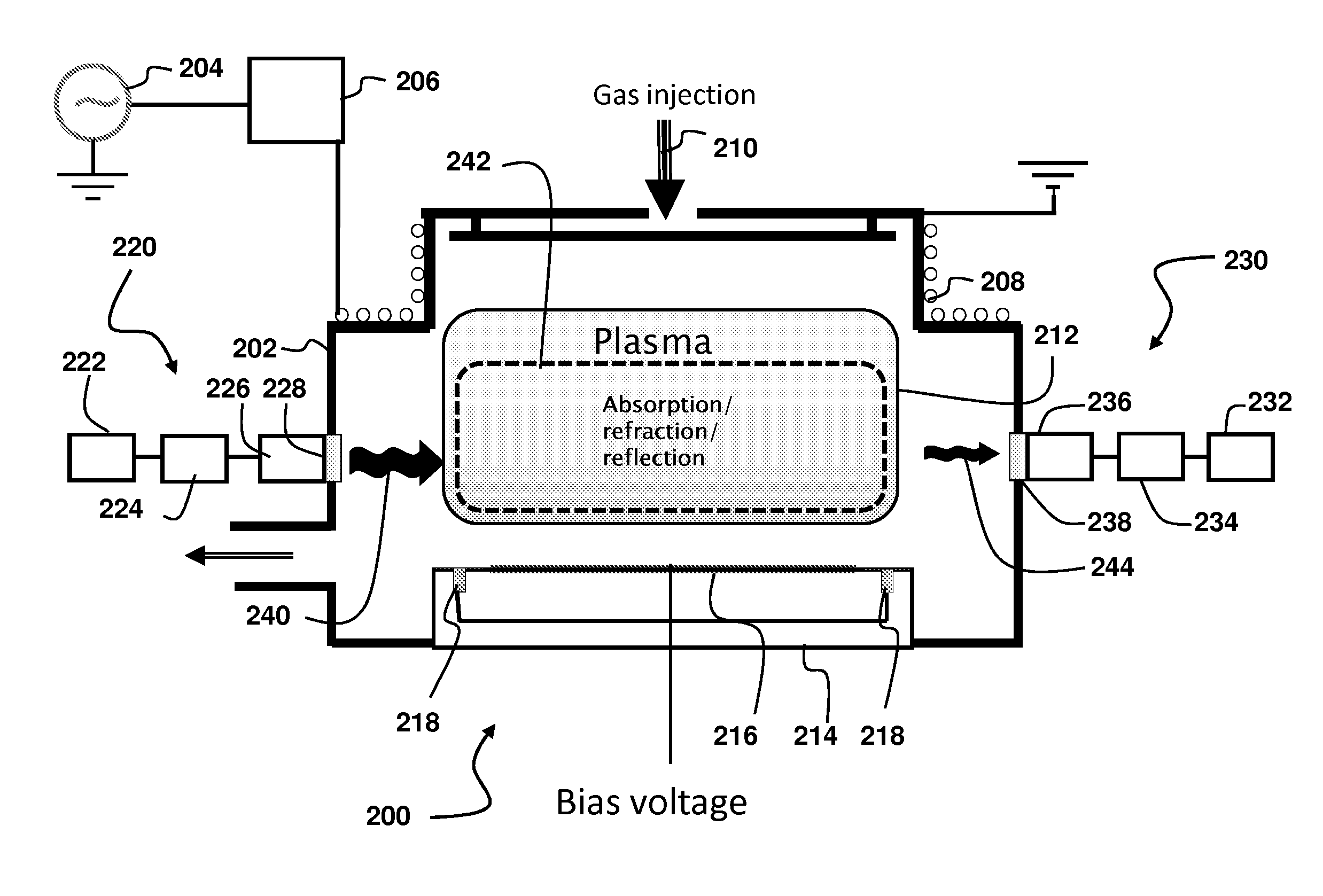
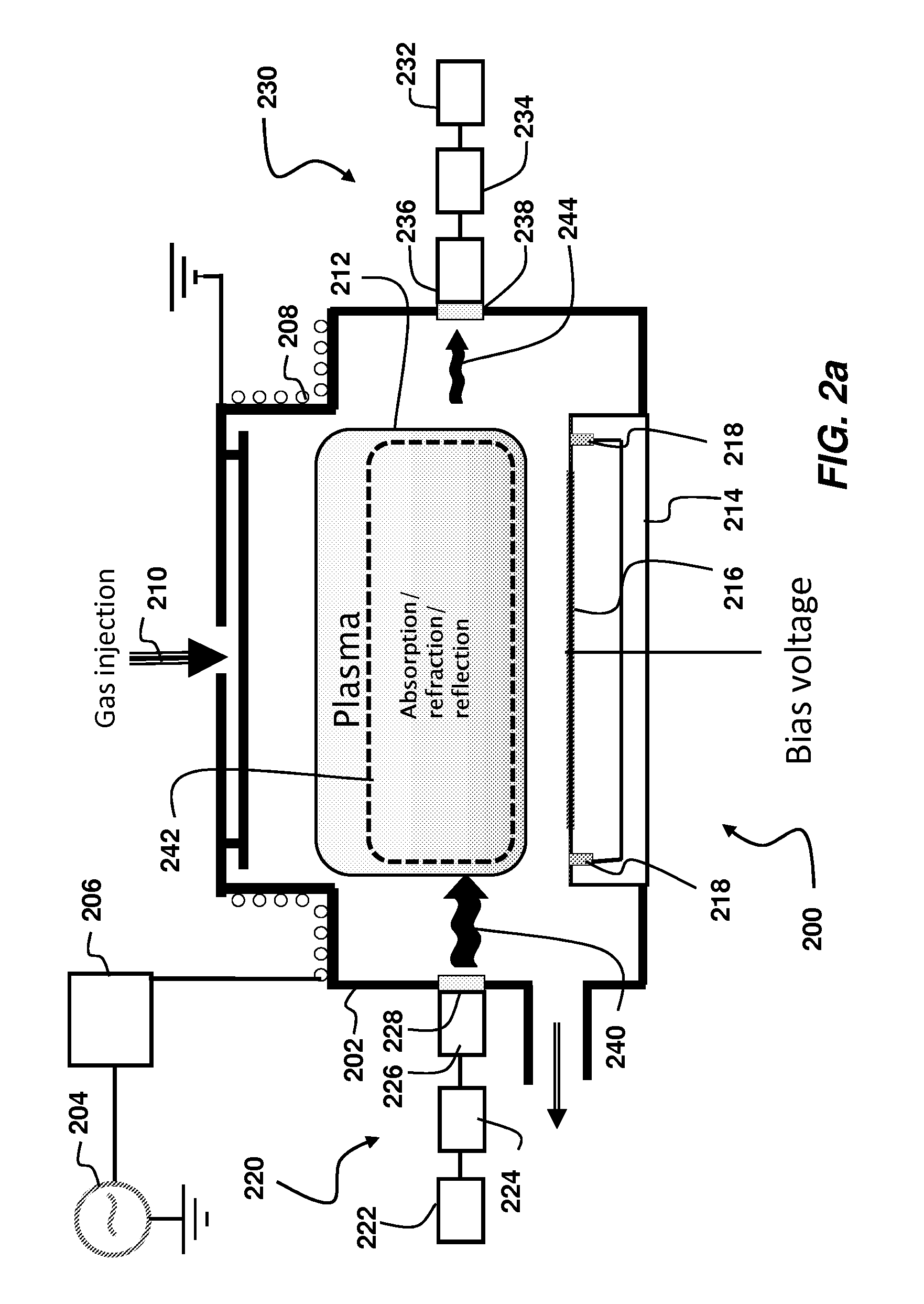
[0008]Embodiments of the present invention are directed to methods and systems for monitoring a plasma. In one embodiment, a plasma detector system comprises a high frequency generator arranged to send incident electromagnetic radiation through a plasma chamber of a plasma system; and a high frequency detection system arranged to detect signal intensity of high frequency radiation sent from the high frequency generator

Problems solved by technology

However, when the plasma is extinguished, applied power may be dissipated in hardware components and may damage components, such as dielectric windows, matching network, and generator.
However, in the case of plasma processes that involve material deposition, the optical window may become opaque after a period of material deposition, causing the optical detection system to fail to properly detect the presence or absence of a plasma.
Accordingly, any anomalies, such as the failure of a plasma to ignite when subject to RF power, may be undetectable.
Even though a plasma is actually present, the optical detector may inadvertently trigger a shutdown of source power if system controls are set to power down when a plasma extinguishes.

Method used


Image

  • System and method for plasma monitoring using microwaves
  • System and method for plasma monitoring using microwaves
  • System and method for plasma monitoring using microwaves

Examples


Embodiment Construction

[0017]The present invention will now be described more fully hereinafter with reference to the accompanying drawings, in which preferred embodiments of the invention are shown. This invention, however, may be embodied in many different forms and should not be construed as limited to the embodiments set forth herein. Rather, these embodiments are provided so that this disclosure will be thorough and complete, and will fully convey the scope of the invention to those skilled in the art. In the drawings, like numbers refer to like elements throughout.

[0018]To solve the deficiencies associated with the methods noted above, novel and inventive techniques and systems for detecting a plasma are introduced. In particular, the present disclosure involves techniques for monitoring a plasma using high frequency radiation. As used herein the term “high frequency radiation” refers to electromagnetic radiation having frequency (or wavelength) generally in the microwave range or the very high freq...


PUM


Abstract

A plasma detector system may include a high frequency generator arranged to send incident electromagnetic radiation through a plasma chamber of a plasma system; and a high frequency detection system arranged to detect signal intensity of high frequency radiation sent from the high frequency generator and transmitted through the plasma chamber.

Description

BACKGROUND OF THE INVENTION[0001]1. Field of the Invention[0002]Embodiments of the invention relate to the field of plasma processing. More particularly, the present invention relates to a method and system for monitoring plasmas.[0003]2. Discussion of Related Art[0004]In plasma-based processing tools, power is input through a series of hardware components that couple the power into a plasma. When the plasma is ignited a large fraction of the input power may be dissipated into the plasma, which serves as a load. However, when the plasma is extinguished, applied power may be dissipated in hardware components and may damage components, such as dielectric windows, matching network, and generator. It may therefore be desirable to monitor a plasma to minimize the time during which a plasma is absent while power is being generated.[0005]In many known plasma systems, detectors, such as optical detectors, are used to aid in monitoring the plasma in a plasma processing chamber. Such detector...

Claims


Application Information

Patent Timeline
IPC IPC(8): G01N21/00B05C11/00H01J7/00
CPCH01J37/32935
Inventor HADIDI, KAMAL
Owner VARIAN SEMICON EQUIP ASSOC INC
Learn More