
Electrical connector

a technology of electrical connectors and connectors, applied in the direction of coupling contact members, coupling device connections, coupling parts engagement/disengagement, etc., can solve the problems of unaddressed need in the art, and the inability to use whole electrical connectors

Active Publication Date: 2012-10-04
LOTES
View PDF8 Cites 6 Cited by
  • Summary
  • Abstract
  • Description
  • Claims
  • Application Information

AI Technical Summary

Benefits of technology

[0016]Further, when the cover slides along the direction opposite to the first direction, the terminal is not pushed by an external force, and only springs upward due to elasticity thereof, so that the contact portion shifts upward to push the mating element to a predetermined height.
[0023]As compared with the related art, in the present invention, among other things, when the cover slides along the first direction, as the stopping portion of the terminal limits upward displacement of the pressed surface of the cover, upward warping of the cover is limited, thereby ensuring the performance of the electrical connector.

Problems solved by technology

In the connector of such a structure, when the cover slides relative to the body, the cover is easily excessively warped upward and thus cannot complete the task, or even the structure of the cover is easily broken due to excessive upward warping, resulting in that the whole electrical connector cannot be used any more.
Therefore, a heretofore unaddressed need exists in the art to address the aforementioned deficiencies and inadequacies.

Method used


Image

  • Electrical connector
  • Electrical connector
  • Electrical connector

Examples


Embodiment Construction

[0036]The present invention is more particularly described in the following examples that are intended as illustrative only since numerous modifications and variations therein will be apparent to those skilled in the art. Various embodiments of the invention are now described in detail. Referring to the drawings, like numbers indicate like components throughout the views. As used in the description herein and throughout the claims that follow, the meaning of “a”, “an”, and “the” includes plural reference unless the context clearly dictates otherwise. Also, as used in the description herein and throughout the claims that follow, the meaning of “in” includes “in” and “on” unless the context clearly dictates otherwise. Moreover, titles or subtitles may be used in the specification for the convenience of a reader, which shall have no influence on the scope of the present invention.

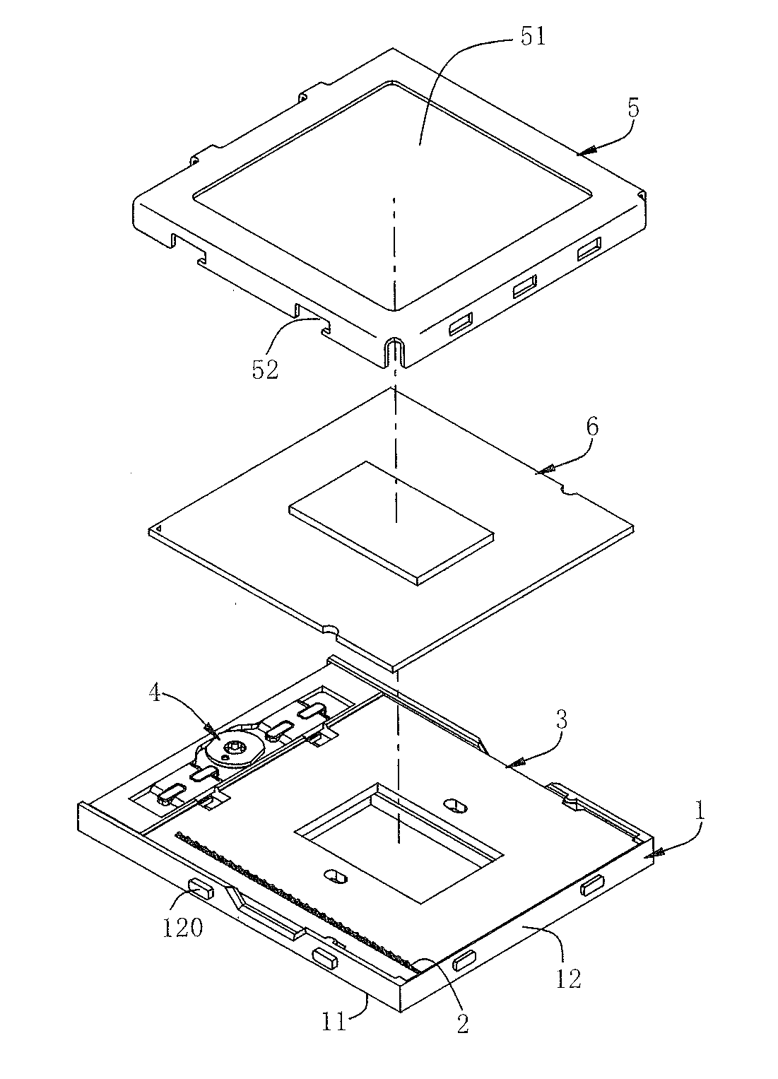
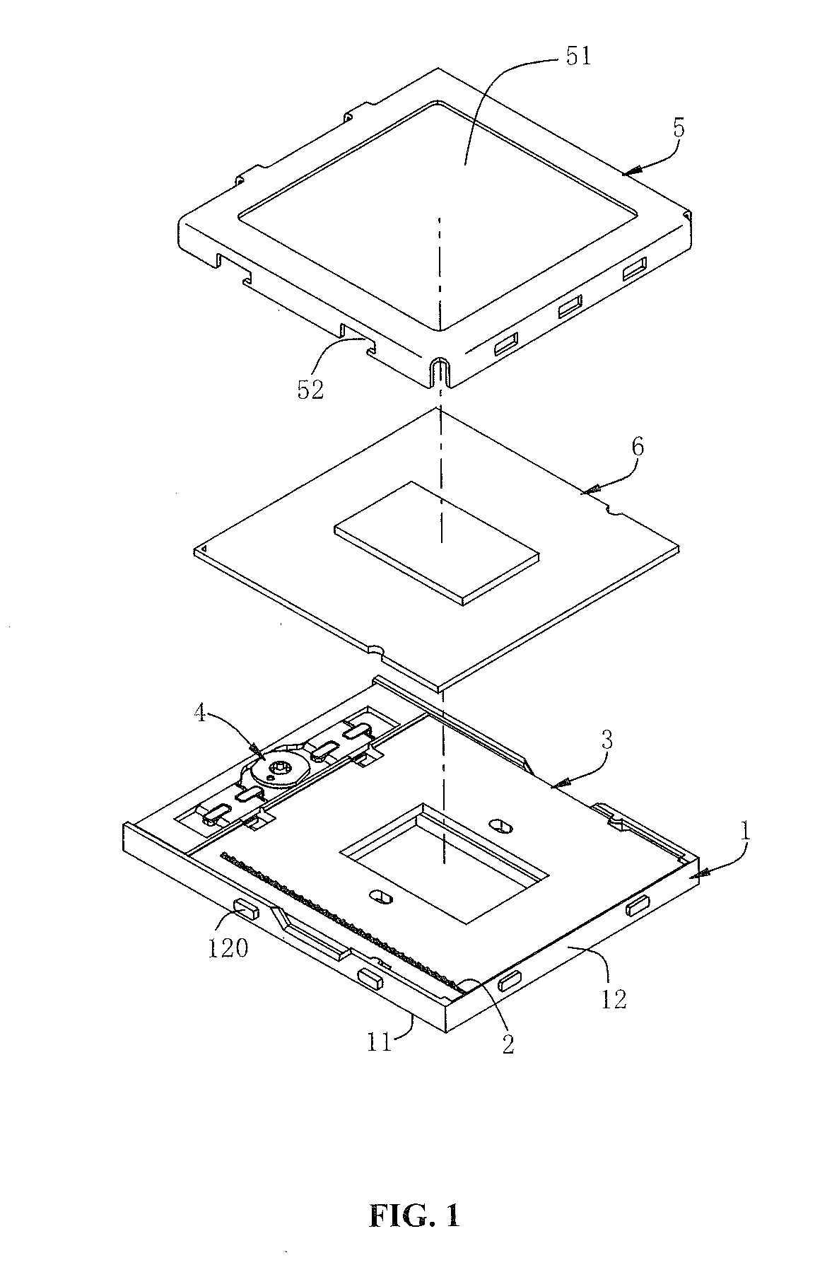
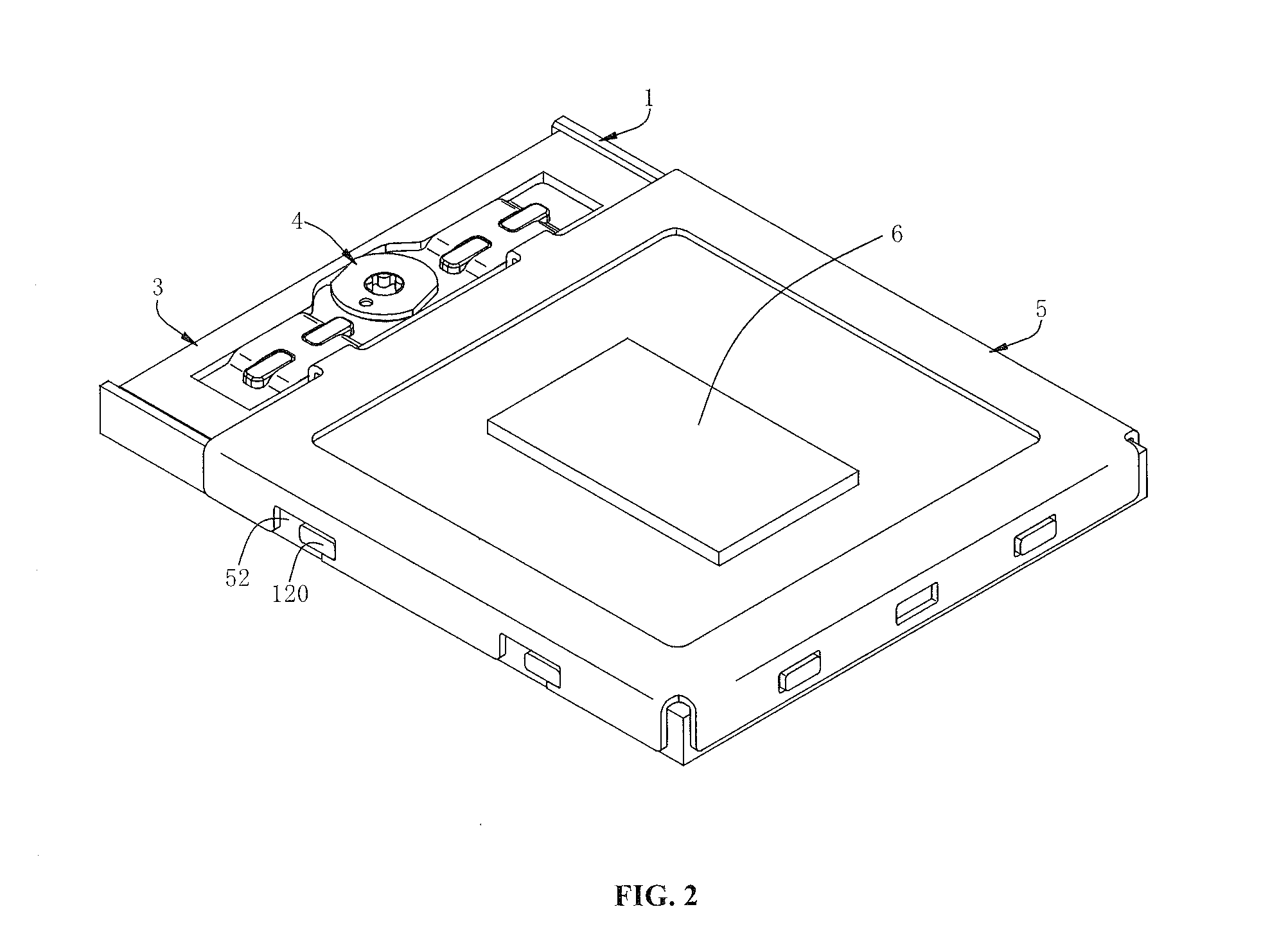
[0037]Referring to FIGS. 1-5, an electrical connector according to a first embodiment of the present invent...


PUM


Abstract

An electrical connector includes a body having a plurality of receiving slots, a plurality of terminals respectively accommodated in the receiving slots, each terminal having a stopping portion, and a cover, slideably covered on the body, and having a plurality of pressed surfaces respectively corresponding to the stopping portions. When the cover slides along a first direction relative to the body, the stopping portion limits upward displacement of the pressed surface, so as to limit upward warping of the cover, thereby ensuring good contact between the terminal and a mating element.

Description

CROSS-REFERENCE TO RELATED APPLICATIONS[0001]This non-provisional application claims priority to and the benefit of, pursuant to 35U.S.C. §119(e), U.S. provisional patent application Ser. Nos. 61 / 470,669, filed Apr. 1, 2011, entitled “ELECTRICAL CONNECTOR ASSEMBLY”, by Ted Ju and Wen Chang Chang, and 61 / 473,607, filed Apr. 8, 2011, entitled “ELECTRICAL CONNECTOR ASSEMBLY”, by Ted Ju and Shang Ju Tsai, the content of which is incorporated herein in its entirety by reference.[0002]Some references, if any, which may include patents, patent applications and various publications, may be cited and discussed in the description of this invention. The citation and / or discussion of such references, if any, is provided merely to clarify the description of the present invention and is not an admission that any such reference is “prior art” to the invention described herein. All references listed, cited and / or discussed in this specification are incorporated herein by reference in their entireti...

Claims


Application Information

Patent Timeline
Patent Type & Authority Applications(United States)
IPC IPC(8): H01R13/62
CPCH01R12/85H01R12/7082
Inventor JU, TEDTSAI, SHANG JU
Owner LOTES
Learn More