
Heat transfer device for residential, commercial, or industrial clothes dryer

Inactive Publication Date: 2012-10-04
ATKINS LISA A
View PDF6 Cites 3 Cited by
  • Summary
  • Abstract
  • Description
  • Claims
  • Application Information

AI Technical Summary

Benefits of technology

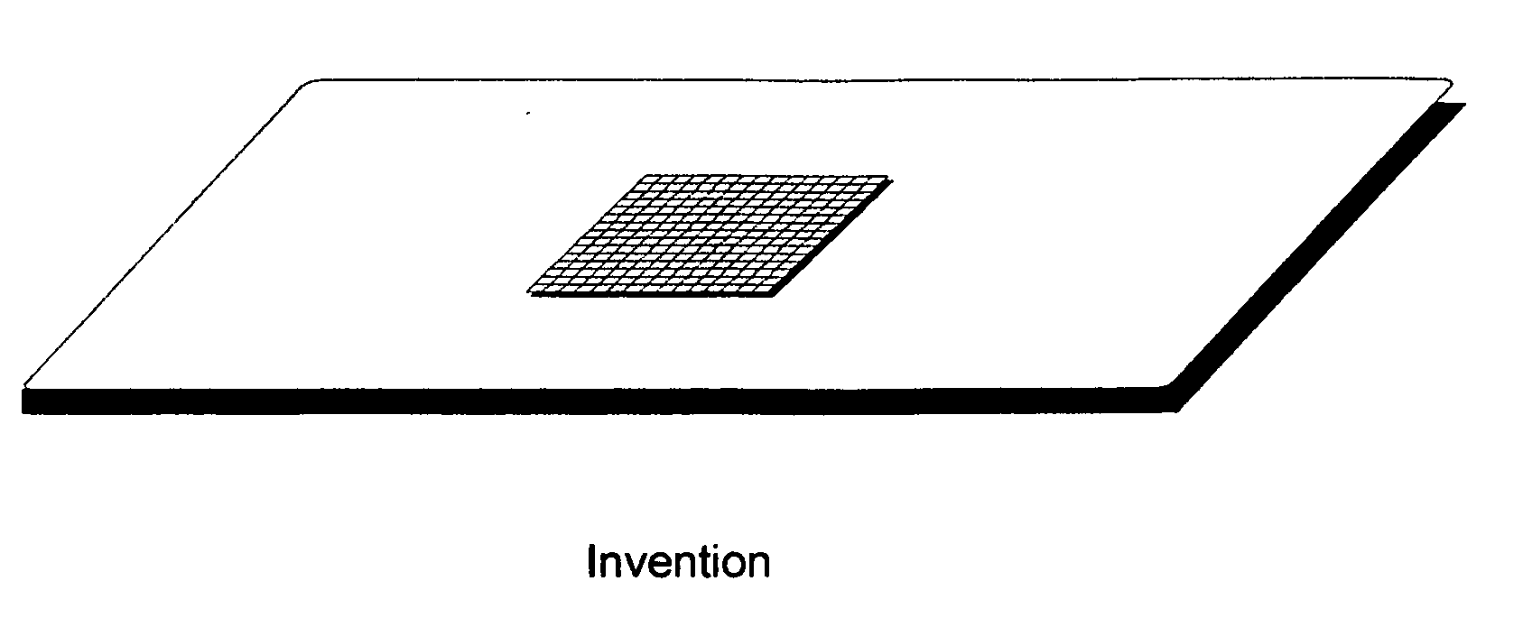
[0012]This invention proposes that when used in conjunction with a Residential, Commercial, or Industrial clothes dryer, it facilitates the removal of moisture from wet laundry by increasing the surface area of heat, which increases the rate of evaporation of moisture. It also achieves this increased evaporation by facilitating the tumbling of the wet load of clothing. In essence, it is a hot element tumbling within a wet load of clothing.

Problems solved by technology

In some instances, the tumbling of the load is limited due to centrifugal force that is generated by the rotation of the drum during operation.
Therefore articles that have limited circulation take more time to dry.

Method used


Image

  • Heat transfer device for residential, commercial, or industrial clothes dryer
  • Heat transfer device for residential, commercial, or industrial clothes dryer

Examples


Embodiment Construction

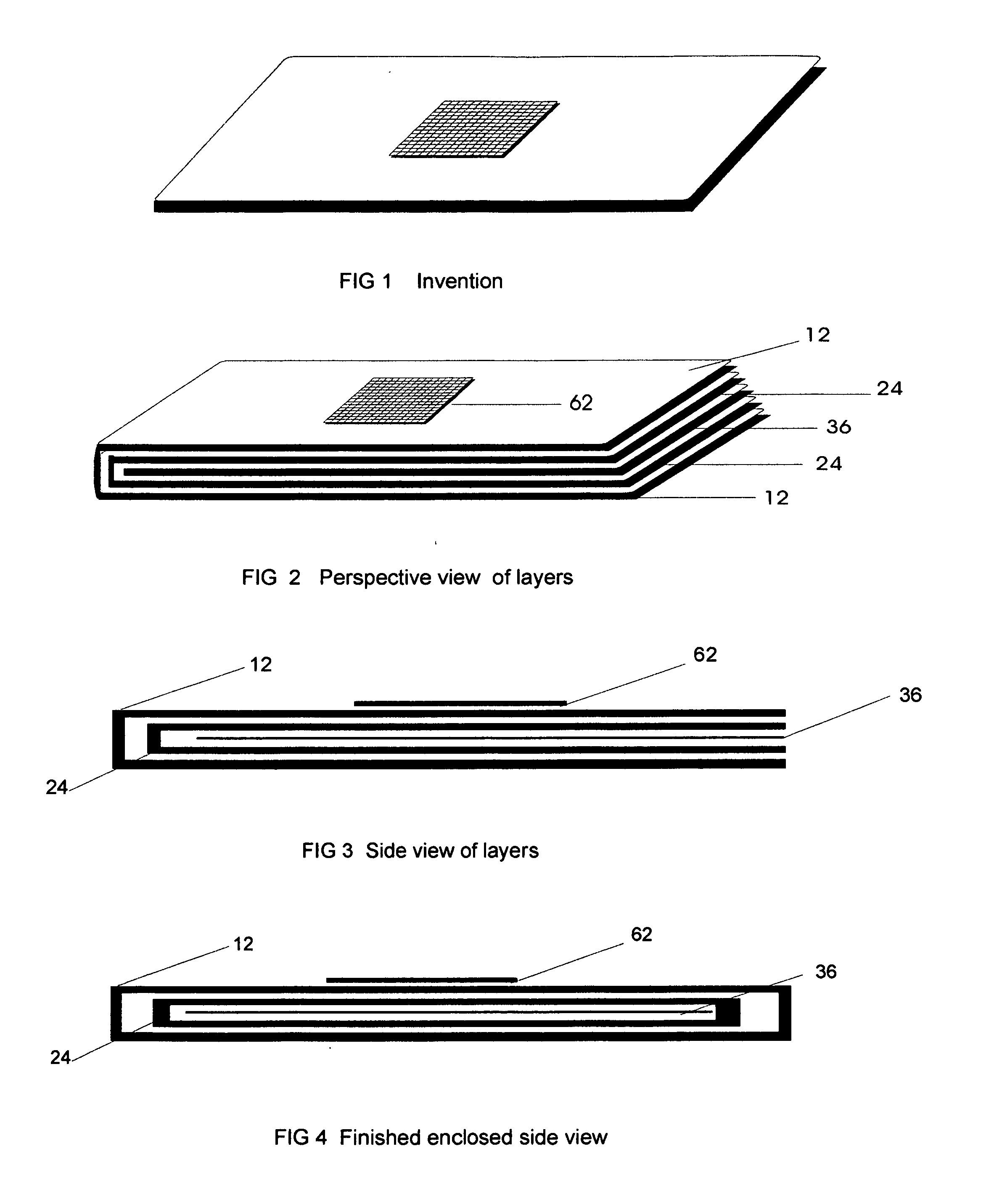
[0028]Generally speaking this invention pertains to a device that accelerates the process of drying a load of wet clothing in a residential, commercial, or industrial clothes dryer. The invention accomplishes the above objective by the following techniques. The device increases the surface area of heat, therefore increasing the rate of evaporation.

[0029]The device also facilitates the tumbling of the clothing, therefore exerting less pressure on the individual items allowing for increased evaporation.

[0030]The device is placed in the tumbler of the dryer in its normal state which is dry. As the dryer is turned on, the device tumbles along with the wet load and quickly absorbs heat from the dryer. The heated device comes in contact with the wet articles of clothing over and over again through the tumbling action of the clothes dryer, speeding up the drying process. The device helps to facilitate the distribution of clothing and hot air throughout the entire space of the dryer, allowi...


PUM


Abstract

This invention relates to an improved method and apparatus for speeding up the drying process in the clothes dryer, saving the consumer time, energy, and the cost of that energy.

Description

CROSS REFERENCE TO RELATED APPLICATIONS[0001]Not applicableSTATEMENT REGARDING FEDERALLY SPONSORED RESEARCH[0002]Not applicableNAMES OR PARTIES TO A JOINT RESEARCH AGREEMENT[0003]Not applicableINCORPORATION BY REFERENCE SUBMITTED ON COMPACT DISC[0004]Not applicableBACKGROUND OF INVENTION[0005]1. Technical Field[0006]The present invention is in the technical field of Heat transfer. More particularly the object of this apparatus is to absorb heat from the clothes dryer as it tumbles and then transfers that heat by coming in contact with the wet articles of clothing, in turn accelerating evaporation and speeding up the drying process.[0007]2. Related Art[0008]Today's clothes dryers consist of a rotating drum known as a tumbler. Hot air is circulated through the tumbler to remove moisture from the wet load. The tumbler rotates to maintain space between the articles to be dried, and this is when evaporation occurs. In some instances, the tumbling of the load is limited due to centrifugal...

Claims


Application Information

Patent Timeline
IPC IPC(8): F26B11/02F26B19/00
CPCF26B3/205D06F58/26F26B11/045
Inventor ATKINS, LISA A.
Owner ATKINS LISA A
Learn More