
Dip joint extension splint and methods of using same

Active Publication Date: 2013-10-03
BARNES DARRYL E M D
View PDF5 Cites 9 Cited by
  • Summary
  • Abstract
  • Description
  • Claims
  • Application Information

AI Technical Summary

Benefits of technology

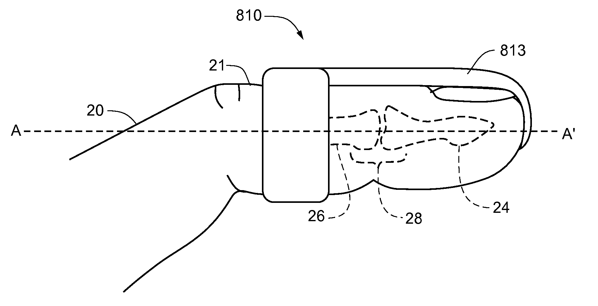
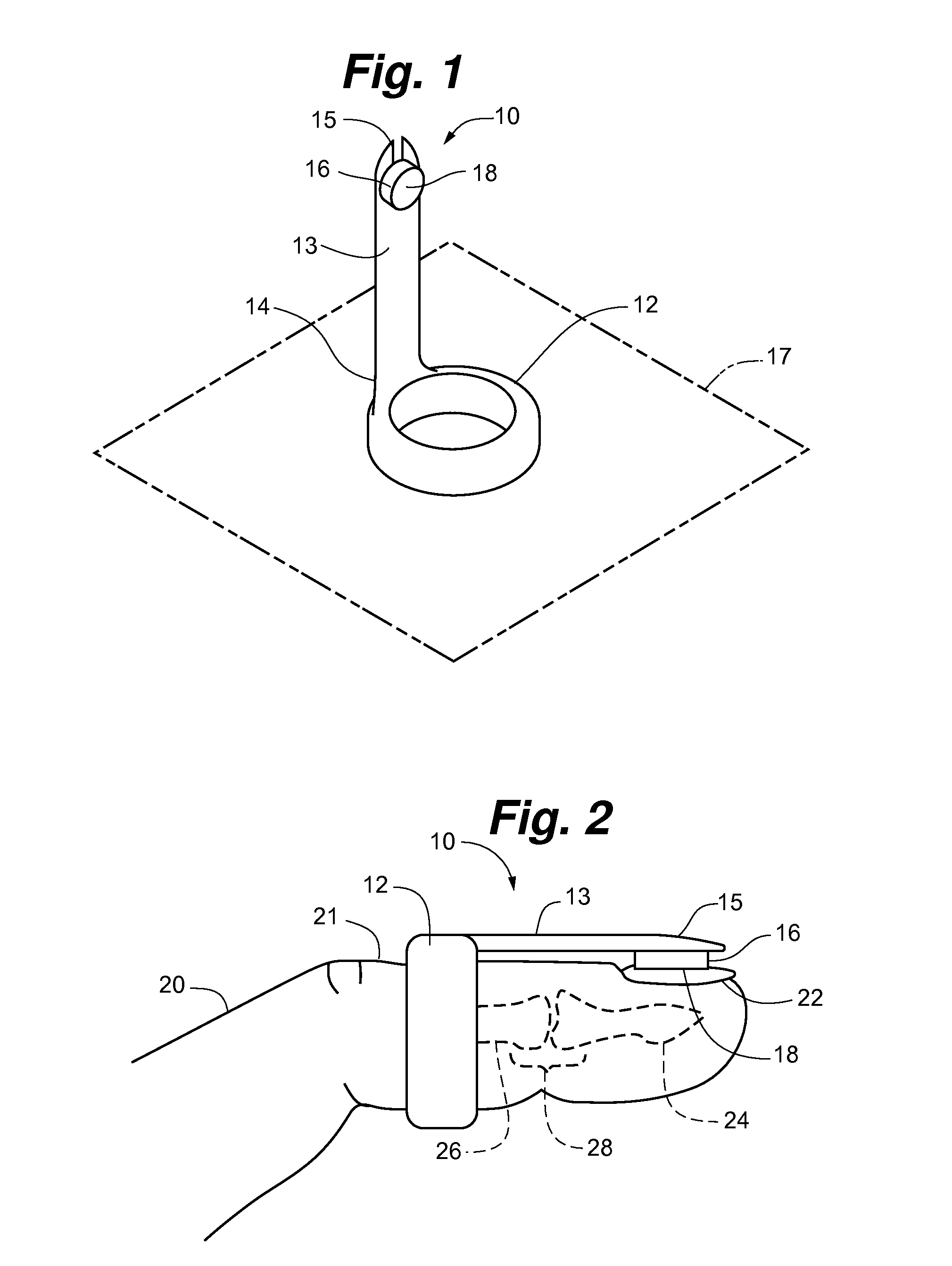
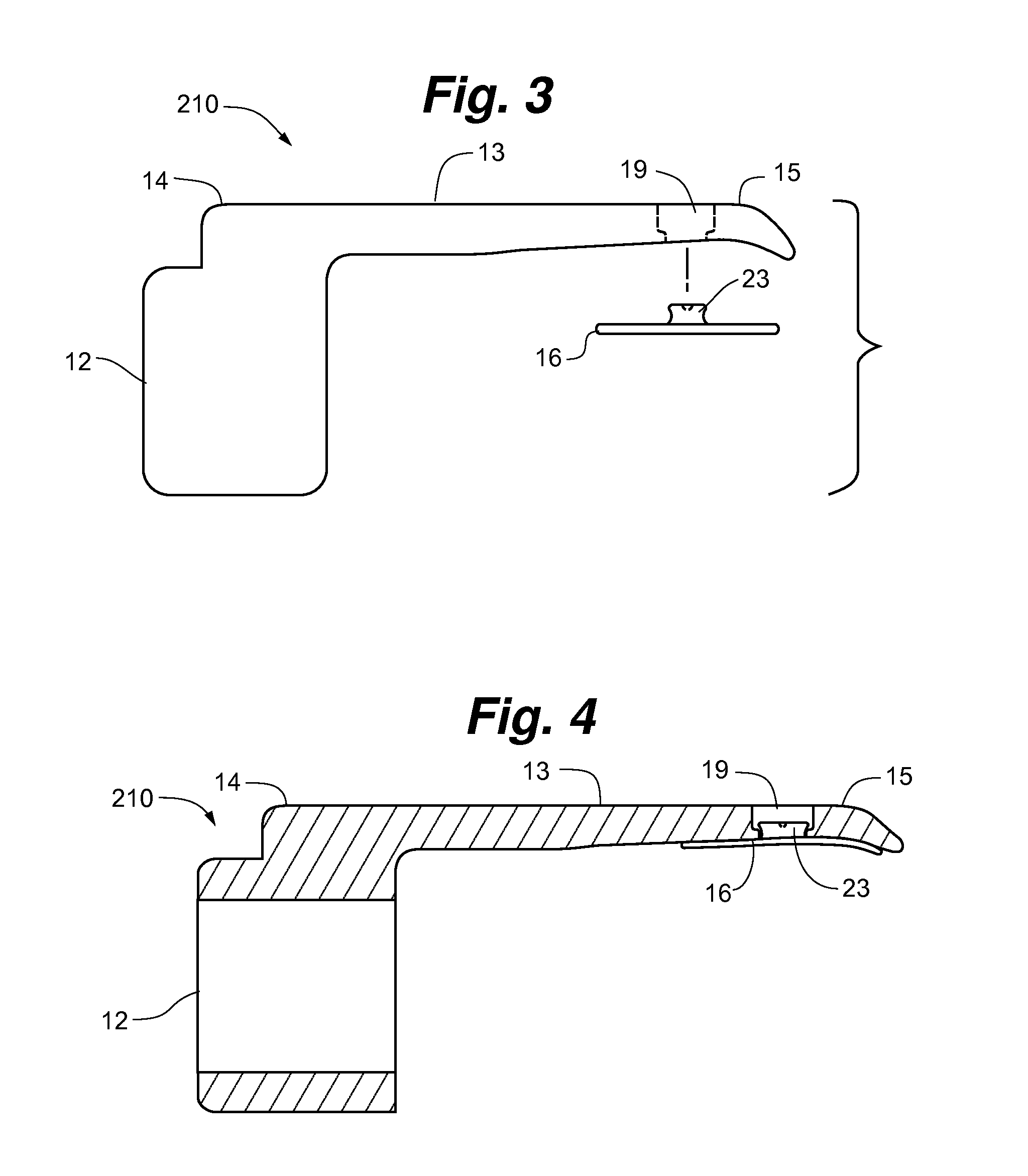
[0025]In certain aspects, the ring elements of the present invention may include an inner portion that comes in contact with the skin and an outer portion, wherein the inner portion and the outer portion comprise different materials. In some aspects, the inner portion includes a material that has a shore hardness that is less than the outer portion. In some aspects, the material of the inner portion is directly connected to the mate

Problems solved by technology

Further, in certain aspects, tape may not need to be used to hold the splint on the finger, which m

Method used


Image

  • Dip joint extension splint and methods of using same
  • Dip joint extension splint and methods of using same
  • Dip joint extension splint and methods of using same

Examples


Example

[0060]While the present invention is amendable to various modifications and alternative forms, specifics thereof have been shown by way of example in the drawings and will be described in further detail below. It should be understood, however, that the intention is not to limit the present invention to the particular exemplary embodiments described. On the contrary, the intention is to cover all modifications, equivalents, and alternatives falling within the spirit and scope of the present invention as defined by the appended claims.

DETAILED DESCRIPTION OF THE DRAWINGS

[0061]In the following detailed description of illustrative embodiments of the present invention, reference is made to the accompanying drawings which form a part hereof, and in which are shown, by way of illustration, specific embodiments in which the present invention may be practiced. It is to be understood that other embodiments may be utilized and structural changes may be made without departing from the spirit an...


PUM


Abstract

Finger splints for use in connection with distal interphalangeal (DIP) joint fractures are disclosed. The splints include a ring element at least partially positioned around a finger at a location proximal to the distal interphalangeal (DIP) joint and include an extension member that extends over the DIP joint and attaches to the fingernail.

Description

RELATED APPLICATION[0001]The present application claims the benefit of U.S. Provisional Application No. 61 / 619,697, filed Apr. 3, 2012, which is incorporated herein in its entirety by reference.FIELD OF THE INVENTION[0002]The present invention relates to a finger splint. More particularly, the present invention relates to a distal interphalangeal (DIP) joint extension splint.BACKGROUND OF THE INVENTION[0003]A splint is a device used for immobilization or holding a part of the body stable to facilitate healing and protect a wounded body part from further damage. A variety of injuries can be treated with splints, including injuries to fingers such as breaks, fractures, strains and sprains. One such injury is “Mallet Finger,” which may occur when a force is directed at the distal finger resulting in an avulsion of the extensor tendon from the dorsum of the base of the distal phalanx. Currently, there are several splints on the market that are used to treat this injury. Compared to more...

Claims


Application Information

Patent Timeline
IPC IPC(8): A61F5/01
CPCA61F5/05875A61F5/013A61F5/05866A61F5/0118
Inventor BARNES, DARRYL E.
Owner BARNES DARRYL E M D
Learn More