
Pavement crack cleaner

Inactive Publication Date: 2012-10-04
BOARD OF RGT UNIV OF NEBRASKA
View PDF6 Cites 2 Cited by
  • Summary
  • Abstract
  • Description
  • Claims
  • Application Information

AI Technical Summary

Benefits of technology

[0009]The present invention is directed to a mechanical device used to effectively clean pavement cracks and the surrounding area, and thereby prepare pavement cracks and joints for sealing or filling. The device is capable of removing

Problems solved by technology

The traditional procedures for preparing roadway joints and cracks for sealing and / or filling are either largely ineffective, labor intensive, or dangerous.
However, air blasting is not an effective means of cleaning out vegetation and large debris, as well as the thin layer of de-icing chemicals that often coat the pavement of cold weather prone regions.
Lastly, sealants and fillers require the surface of the pavement to be at least 40° F. for proper bonding; as cracks are more often sealed within the freeze-thaw period of winter, air blasting is not a recommended means of sole crack preparation.
However, hot air blasting introduces other problems.
Extreme caution must be taken to ensure the pavement is not overheated, which will result in the asphalt binder becoming brittle and leading to premature failure.
Care should also be taken to never allow for direct flame methods to be used as the charring effect will lead to a soot residue and cause poor initial bonding.
In addition, hot air blasting does not clean de-icing chemicals remaining in and out of the cracks.
Furthermore, propane regulators are often frozen in cold weather, thus delaying the sealing process.
However, there are several drawbacks to the sandblasting method of crack preparation.
The first problem is that it includes two operators: one for the sand blasting, and one for cleaning out the sand left behind.
Although routing is a better approach than the methods above for cleaning cracks, it is not a solution for complete preparation for crack sealing.
Also, routing which generally uses a ⅜″ carbide-tipped rotary impact bit is not effective for wider cracks to clean de-icing chemicals in cracks unless multiple routing paths are used.
Furthermore, many groups hesitate to rout cracks because the routing equipment is very heavy and makes it difficult to follow cracks unless cracks are straight.
It often results in creation of another crack while routing random cracks.
Pulling such heavy equipment downhill or on a windy day often puts the operator in dangerous situations as well.

Method used


Image

  • Pavement crack cleaner
  • Pavement crack cleaner
  • Pavement crack cleaner

Examples


Embodiment Construction

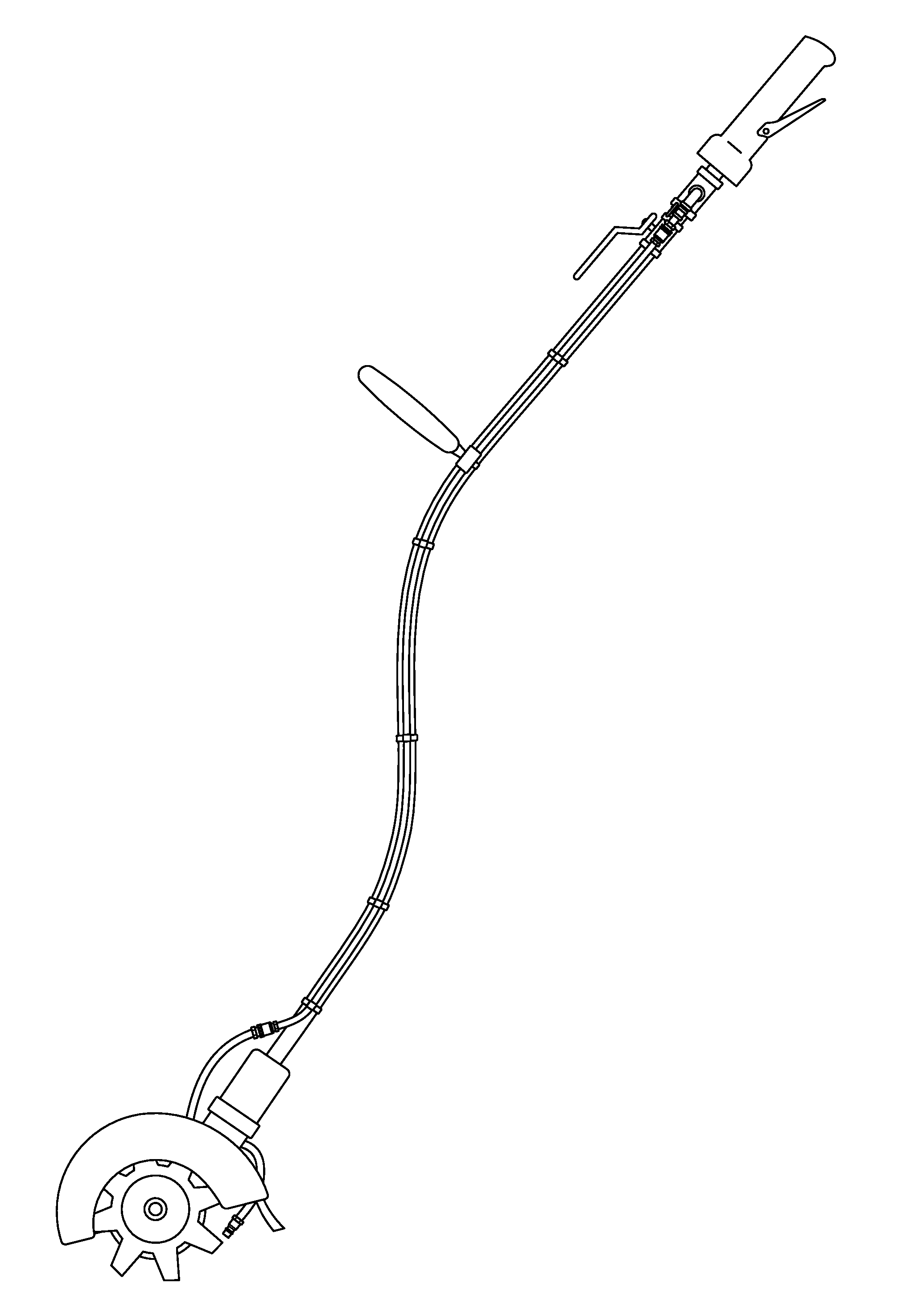
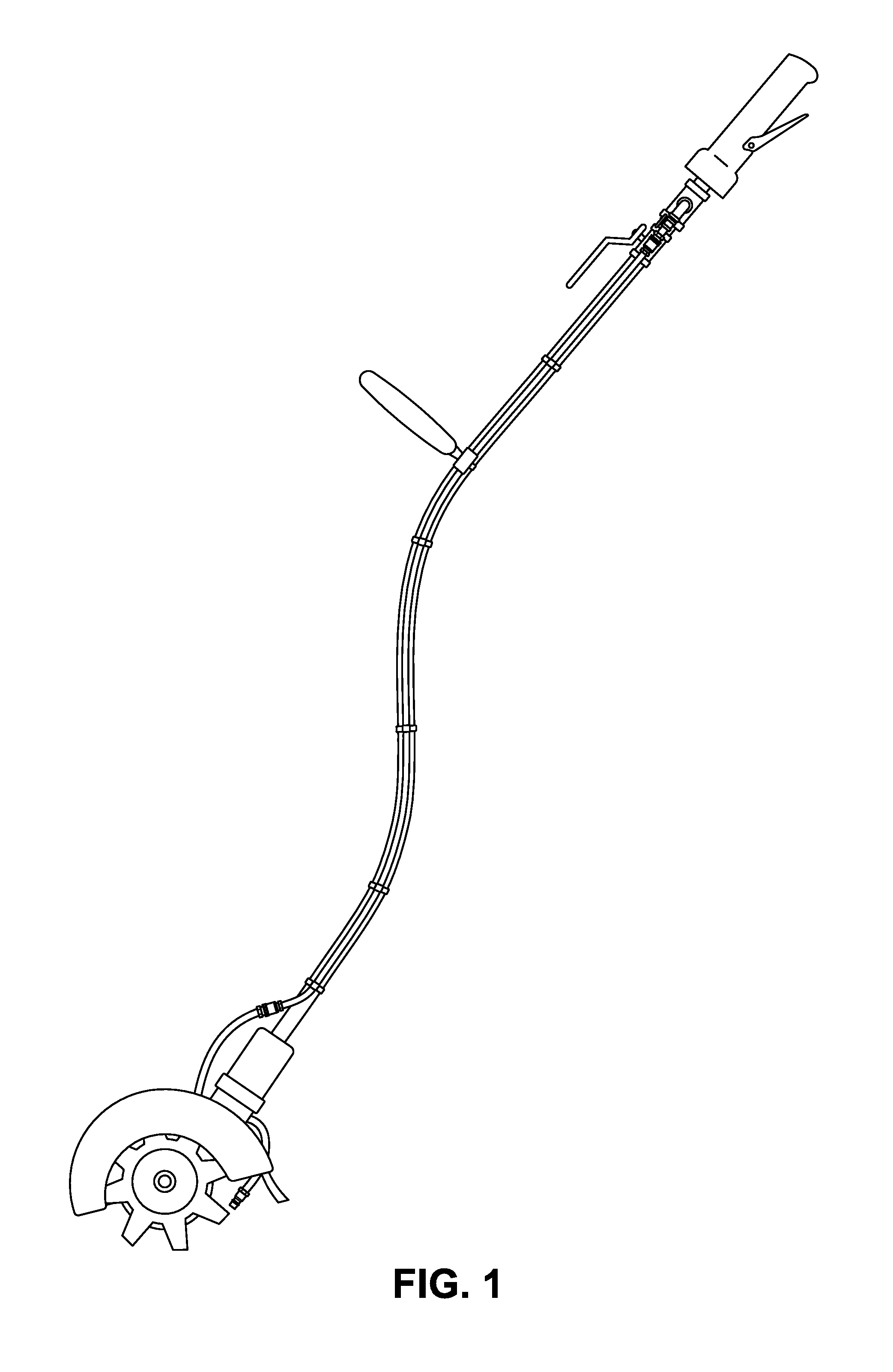
[0017]FIG. 1 is a schematic view showing one of the embodiments of the invention. The lever near the handle at the top of the device allows the user to control the air flow rate to the air blaster. The control switch just below the handle acts to split the air flow between the air blaster and the pneumatically powered motor. The motor is located within the housing just above the guard cover. The guard cover is the semi-circle in the drawing above the pavement router which acts to prevent debris from flying up or to the left of the device as it operates. The primary air blaster nozzle is positioned behind the pavement router.

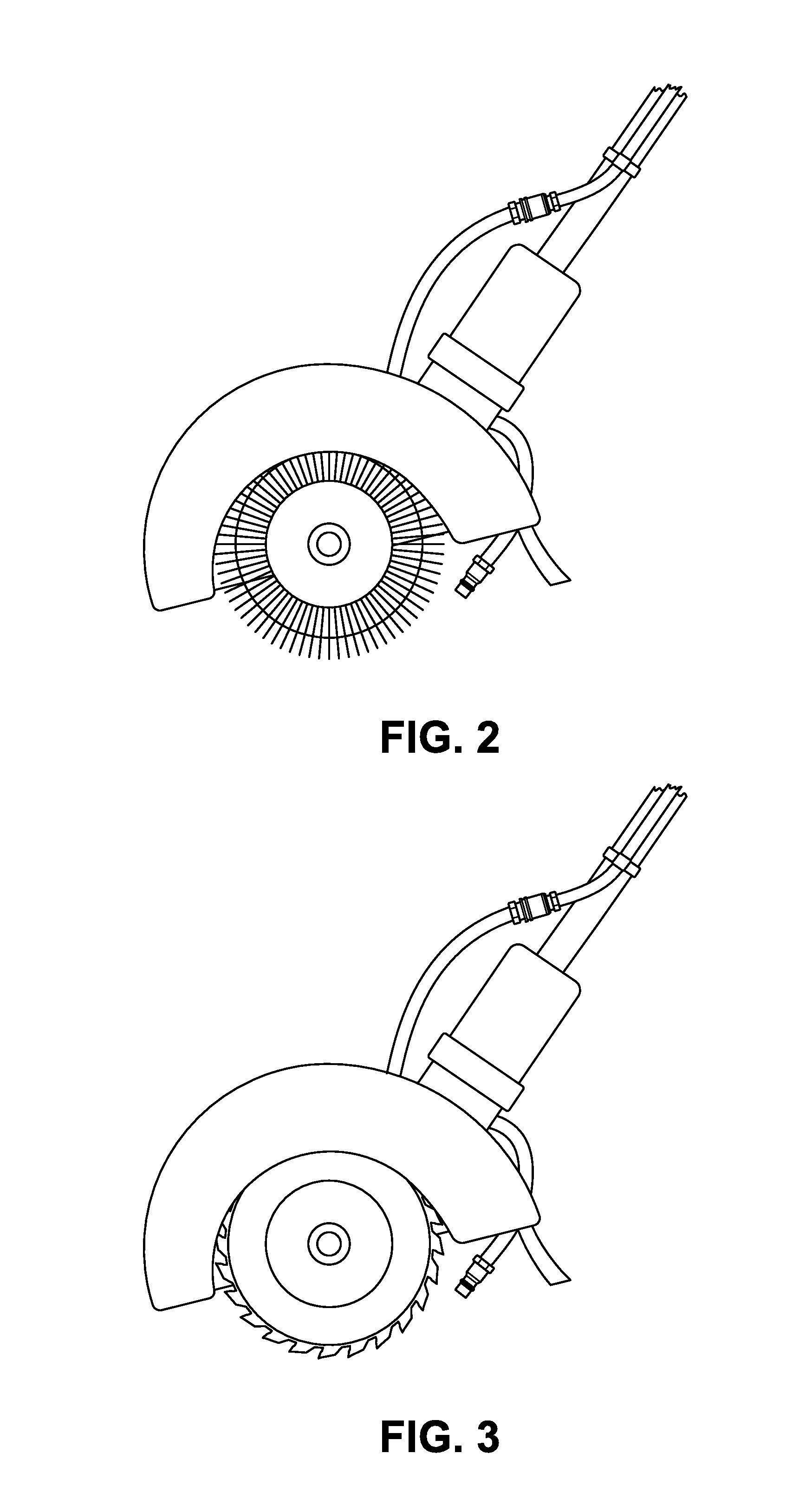
[0018]FIG. 2 is a close-up view of an embodiment showing the wire brush assembly instead of the pavement router. All other aspects of this embodiment are identical to the embodiment in FIG. 1.

[0019]FIG. 3 is a close-up view of an embodiment showing a masonry bit instead of the pavement router. All other aspects of this embodiment are identical to the embodiment i...


PUM


Abstract

Devices for cleaning and preparing pavement cracks for sealing are disclosed. An example device comprises a wire brush assembly for removal of mid and large-sized debris, an air blaster for removal of fine-grained particulate, a heat lance, and a vacuum for controlled removal of debris and particulates. The example device would also have means for attachment to an air compressor.

Description

CROSS-REFERENCE TO RELATED APPLICATION[0001]This application claims priority to U.S. Provisional Application No. 61 / 470,547 entitled “Pavement crack cleaner for sealing,” filed Apr. 1, 2011, which is incorporated herein by reference in its entirety for all purposes.FEDERALLY SPONSORED RESEARCH OR DEVELOPMENT[0002]This invention was made with government support under National Academy of Sciences grant number NCHRP-159. The government has certain rights in the invention.TECHNICAL FIELD[0003]The present disclosure relates generally to cleaning and preparing cracks in pavement for sealing. More specifically, the present disclosure pertains to a device for efficiently and effectively cleaning pavement cracks of debris and de-icing chemicals in preparation for sealing of the pavement cracks.BACKGROUND OF THE INVENTION[0004]Flexible and rigid pavement joints and cracks are sealed or filled to mitigate further damage caused by the infiltration of water and foreign debris. Crack sealing is g...

Claims


Application Information

Patent Timeline
IPC IPC(8): A47L5/14A47L9/00A47L9/04
CPCE01H11/00A01M21/02
Inventor CHO, YONG
Owner BOARD OF RGT UNIV OF NEBRASKA
Learn More