Eureka AIR delivers breakthrough ideas for toughest innovation challenges, trusted by R&D personnel around the world.

Signal processing method, device, and system in a passive optical network

Inactive Publication Date: 2012-09-13
HUAWEI TECH CO LTD
View PDF0 Cites 26 Cited by
  • Summary
  • Abstract
  • Description
  • Claims
  • Application Information

AI Technical Summary

Benefits of technology

[0011]Embodiments of the present invention provide a signal processing method, device, and system in a passive optical network to increase the transmission distance and reduce the cost of network construction.
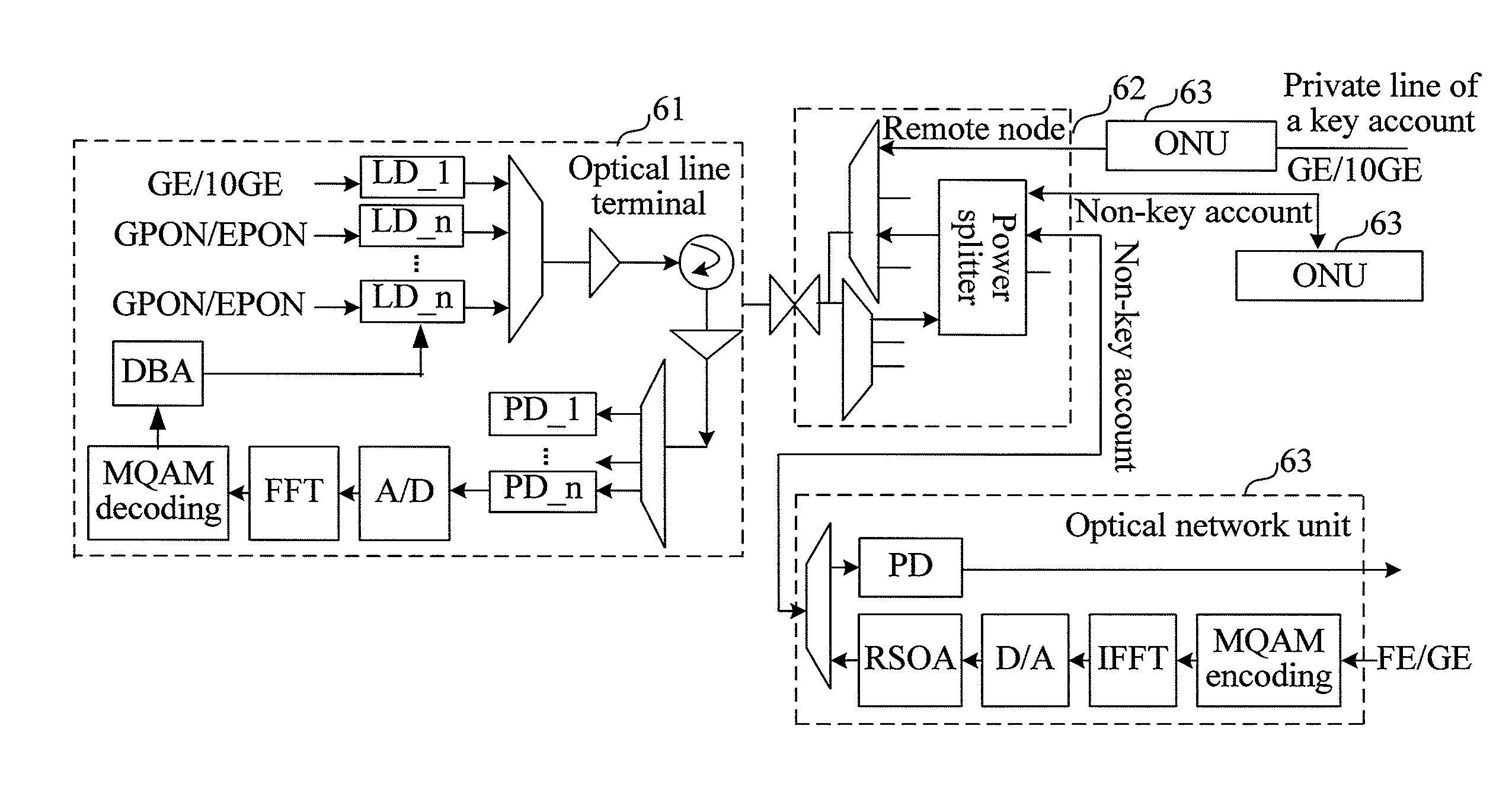
[0036]Through the signal processing method, device and system of the passive optical network provided by the embodiments of the present invention, the received service signal is modulated onto allocated Orthogonal Frequency Division Multiple Access subcarriers, and digital / analog conversion is performed on the modulated Orthogonal Frequency Division Multiple Access subcarriers to obtain an electric domain Orthogonal Frequency Division Multiple Access signal; then the electric domain Orthogonal Frequency Division Multiple Access signal is modulated onto the uplink optical signal; afterwards, optical signals are superposed and multiplexed through the remote node to obtain a continuous multi-wavelength optical signal. As the optical power compensation for continuous signals is easy, long-distance transmission can be supported. Moreover, because the cost of transmitters and receivers of the continuous signal is lower than that of the burst signal, the cost of network construction is reduced.

Problems solved by technology

However, the current WDM PON does not meet such technical requirements.
The quantity of wavelengths demultiplexed by the WDM PON is limited.
For example, 40 wavelengths available exist at the C band of the WDM PON and it is hard to increase the quantity.
If each user is allocated an independent wavelength, the quantity of served users is limited.
Since each ONU in the WDM PON uses one wavelength exclusively, the sharing of the wavelength is undesirable.
The wavelength of one ONU cannot be used by another ONU even if the wavelength is not in use, which is a waste of wavelength resources.
Due to a burst frame structure of the uplink TDMA, it is hard to implement optical power compensation in the uplink whether it is implemented by an Erbium-doped Optical Fiber Amplifier (Erbium-doped Optical Fiber Amplifier, EDFA) or a Semiconductor Optical Amplifier (Semiconductor Optical Amplifier, SOA).
Therefore, the PON with the mixture of WDM and TDM cannot implement long-distance transmission.
The cost of network construction is high.

Method used


Image

  • Signal processing method, device, and system in a passive optical network
  • Signal processing method, device, and system in a passive optical network
  • Signal processing method, device, and system in a passive optical network

Examples


first embodiment

[0095]FIG. 10 is a flowchart of a signal processing method in a passive optical network according to the present invention. As shown in FIG. 10, the signal processing method of the passive optical network includes the following steps.

[0096]Step 101: Perform baseband encoding processing on a received service signal.

[0097]Step 102: Modulate the service signal after baseband encoding processing onto allocated Orthogonal Frequency Division Multiple Access subcarriers through an Orthogonal Frequency Division Multiplexing modulation manner.

[0098]Step 103: Perform digital / analog conversion on the modulated Orthogonal Frequency Division Multiple Access subcarriers to obtain an electric domain Orthogonal Frequency Division Multiple Access signal.

[0099]Step 104: Modulate the electric domain Orthogonal Frequency Division Multiple Access signal onto an uplink optical signal to obtain an optical domain Orthogonal Frequency Division Multiple Access signal.

[0100]Step 105: Transmit the optical doma...

second embodiment

[0113]FIG. 11 is a flowchart of a signal processing method in a passive optical network according to the present invention. As shown in FIG. 11, the signal processing method of the passive optical network includes the following steps.

[0114]Step 201: Perform analog / digital conversion on received superposed optical domain Orthogonal Frequency Division Multiple Access signals.

[0115]Step 202: Perform Orthogonal Frequency Division Multiplexing demodulation on the signals after analog / digital conversion.

[0116]Step 203: Perform baseband decoding processing on the signals after Orthogonal Frequency Division Multiplexing demodulation to obtain service signals.

[0117]The OLT may include multiple receivers. The WDM demultiplexer of the OLT demultiplexes a multi-wavelength optical signal received from the RN into superposed optical domain OFDMA signals of different wavelengths. The receivers may receive the superposed optical domain OFDMA signals respectively; the OLT performs analog / digital (A / ...

third embodiment

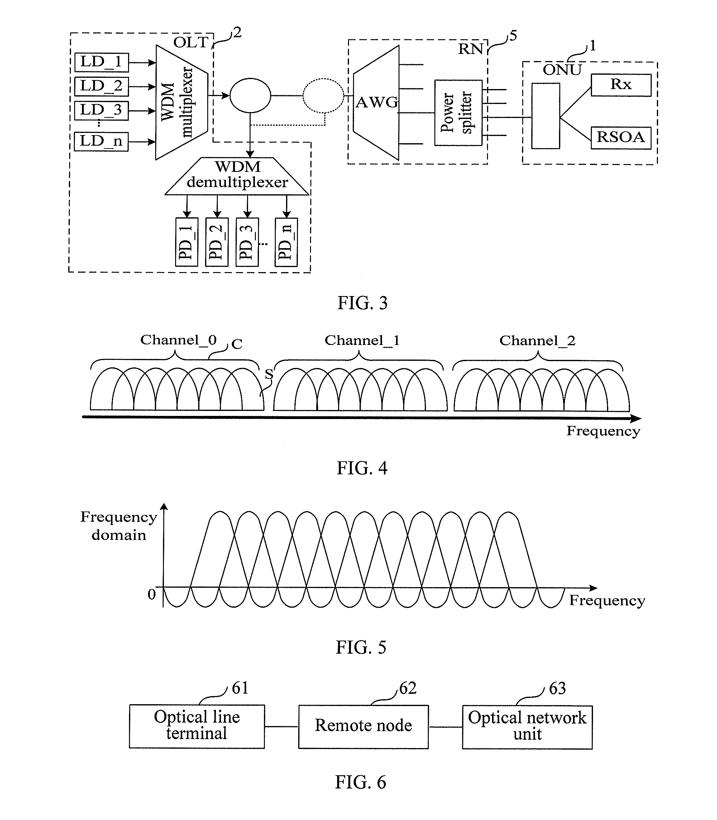
[0126]The ONUs in one group share the wavelength through the OFDMA subcarriers allocated by the OLT. Specifically, different quantities of OFDMA subcarriers with different serial numbers are allocated to different ONUs in one group and the electric domain OFDMA signals on OFDMA subcarriers of the group are modulated to optical domain OFDMA signals of one wavelength. The optical domain OFDMA signals of one wavelength are then superposed by a power splitter. One or more than one OFDMA subcarrier is allocated to one ONU in the uplink. A power splitter superposes, on one wavelength, the OFDMA subcarriers of all ONUs connected with the power splitter in the frequency domain and the time domain into one OFDMA frame. FIG. 12b is a schematic diagram of OFDMA subcarriers superposed on one the same wavelength in the signal processing method of the passive optical network according to the present invention. As shown in FIG. 12b, OFDMA subcarrier A is allocated to ONU_1, OFDMA subcarrier B is a...


PUM


Abstract

A signal processing method, device, and system in a passive optical network are provided. The signal processing method in the passive optical network includes: performing baseband encoding processing on a received service signal; modulating the service signal after baseband encoding processing onto allocated Orthogonal Frequency Division Multiple Access subcarriers through an Orthogonal Frequency Division Multiplexing modulation manner; performing digital / analog conversion on the modulated OFDMA subcarriers to obtain an electric domain Orthogonal Frequency Division Multiple Access signal; modulating the electric domain Orthogonal Frequency Division Multiple Access signal to an uplink optical signal to obtain an optical domain Orthogonal Frequency Division Multiple Access signal; and transmitting the optical domain Orthogonal Frequency Division Multiple Access signal.

Description

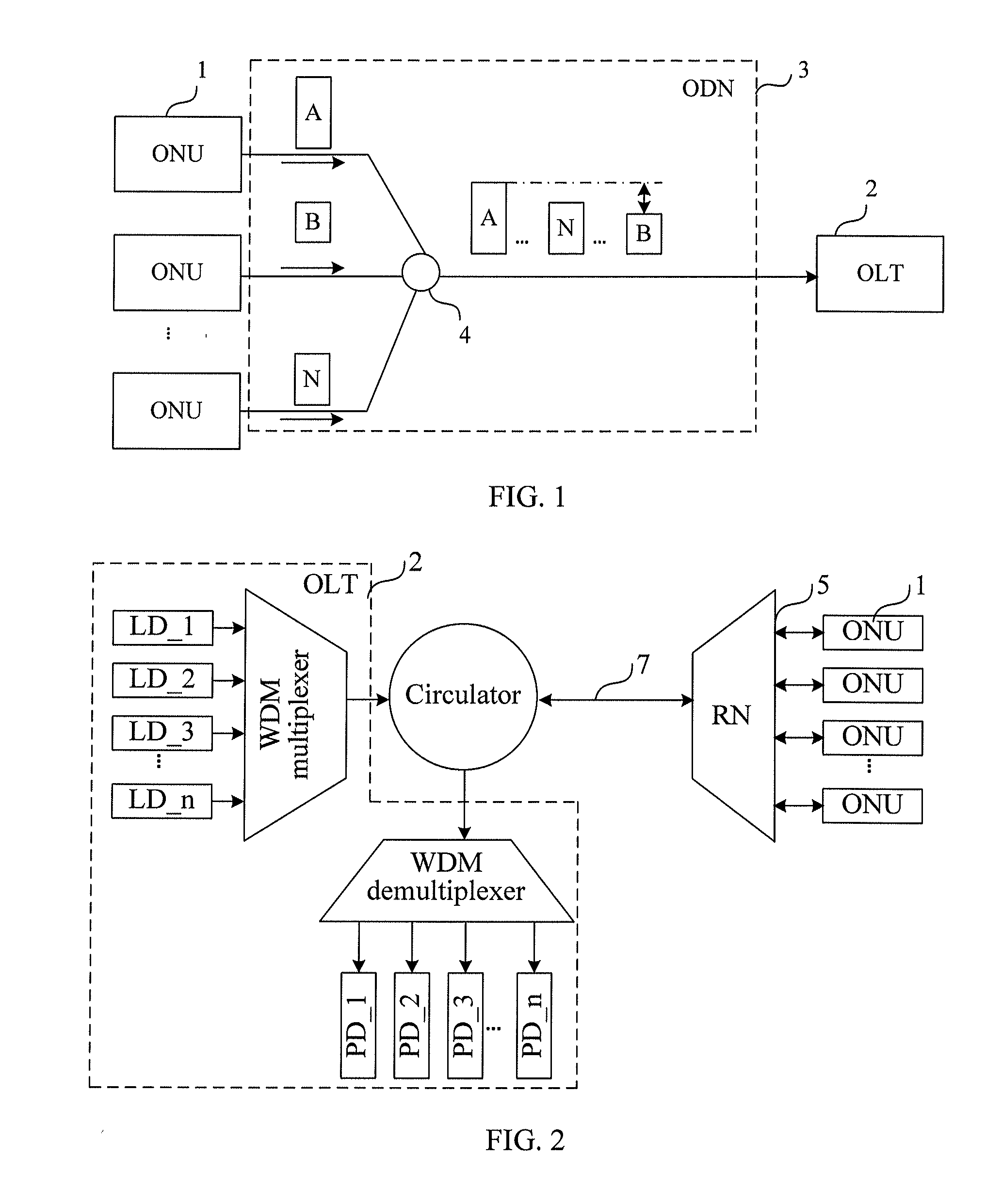
CROSS-REFERENCE TO RELATED APPLICATIONS[0001]This application is a continuation of International Application No. PCT / CN2010 / 078942, filed on Nov. 22, 2010, which claims priority to Chinese Patent Application No. 200910226175.3, filed on Nov. 24, 2009, both of which are hereby incorporated by reference in their entireties.FIELD OF THE INVENTION[0002]The present invention relates to the field of communications technologies, and in particular, to a signaling processing method, device, and system in a passive optical network.BACKGROUND OF THE INVENTION[0003]A passive optical network (Passive Optical Network, PON) is a broadband optical access technology and has a point-to-multipoint physical topology structure. FIG. 1 is a schematic structure diagram of a PON network in a prior art. As shown in FIG. 1, the PON network includes an optical line terminal (Optical Line Terminal, OLT), an optical distribution network (Optical Distribution Network, ODN), and multiple optical network units (Op...

Claims


Application Information

Patent Timeline
IPC IPC(8): H04J14/00H04B10/272
CPCH04B10/272H04J14/0282H04J14/0298H04L5/0007H04L27/2096H04J14/0246H04L27/2697H04J14/025H04J14/0252H04J14/0265H04J2014/0253H04L27/2627
Inventor ZOU, SHIMIN
Owner HUAWEI TECH CO LTD
Why Eureka
Eureka Blog
Learn More