
Apparatus and method for determining a location in a target image

Inactive Publication Date: 2012-08-30
UCL BUSINESS PLC
View PDF2 Cites 52 Cited by
  • Summary
  • Abstract
  • Description
  • Claims
  • Application Information

AI Technical Summary

Benefits of technology

[0013]In one embodiment, for each reference image the epipolar projection produces an epipolar line representing the projection in the target image of the location of the site in the reference image. If there are two reference images, the determined location for the site in the target image corresponds to the intersection of the two epipolar lines produced for the two reference images. If there are three or more reference images, the determined location for the site in the target image can be based on minimising a measure of distance from the three or more epipolar lines produced for the three reference images.
[0025]The approach described herein is based on the computation in the target image of a point's location as the intersection of two epipolar lines derived from the location of corresponding sites two or more previously acquired images. The epipolar geometry is recovered with a robust technique. Such an approach has several advantages. It provides a robust and reliable solution to track sites in any procedure. An initialization process can be used to give a starting point based on a tracking device, and a refinement process can then be used to obtain an accurate re-localisation position based on the geometric constraints between multiple images. The method also reduces the number of computations for the re-localization, since it only involves consideration of epipolar lines, without requiring the determination of spatial transformations between the images. Therefore, the method can track / re-localise a site with no or minimal interaction. In contrast, for many existing endoscopic re-localisation methods, the physicians need to make a visual inspection to identify the positions and sometimes have to utilise markers to assist the procedure. Furthermore, the method should work efficiently in real-time, such as for use in a real-time guidance system, based on a information coming from the endoscopic images and the electromagnetic tracking device. If no pre-operative images are used, no camera tracking and / or registration is involved, but rather, sites may be tracked directly in the endoscopic video images.
[0027]Note that the use of epipolar geometry is already known in a medical context, see for example Hu M. et al., “3D reconstruction of internal organ surfaces for minimal invasive surgery”, 2007, Medical Image Computing and Computer Assisted Intervention (MICCAI'07), Vol. 4791 of Lecture Notes in Computer Science, pp. 68-77, Springer-Verlag, but for different applications (not for re-localization). The present approach focuses on biopsy site re-localisation (and other analogous problems), which is concerned with spatial transformations (rotations and translations) between successive endoscopic images. As described herein, these spatial transformations can be efficiently accommodated with the recovery of the epipolar geometry formed by different endoscopic images.

Problems solved by technology

Significant problems for many endoscopies are biopsy site detection, path planning to reach the site, and re-localisation (re-identification) of the site during the same or a future examination.
However, it is difficult in practice to have a good match between a tissue sample extracted for histology and the extent scanned during optical biopsy.
As a result, many extracted samples may present irrelevant information, which brings great difficulties to the clinicians to diagnose, screen, stage and treat diseases.
A significant problem for applications in endoscopy procedures based on video images only and for gastroscopy in particular is that biopsies are performed by interactive guidance of the forceps by the endoscopist.
However, these documents focus only on tracking the instrument tip and its trajectory for robotized-assisted surgeries.
In addition, similar problems also apply to non-medical applications such as industrial inspection; remote sensing in hostile environments or very remote sites, for example, underground or underwater, or in space exploration; remote manipulation and repair; and telerobotics.

Method used


Image

  • Apparatus and method for determining a location in a target image
  • Apparatus and method for determining a location in a target image
  • Apparatus and method for determining a location in a target image

Examples


Embodiment Construction

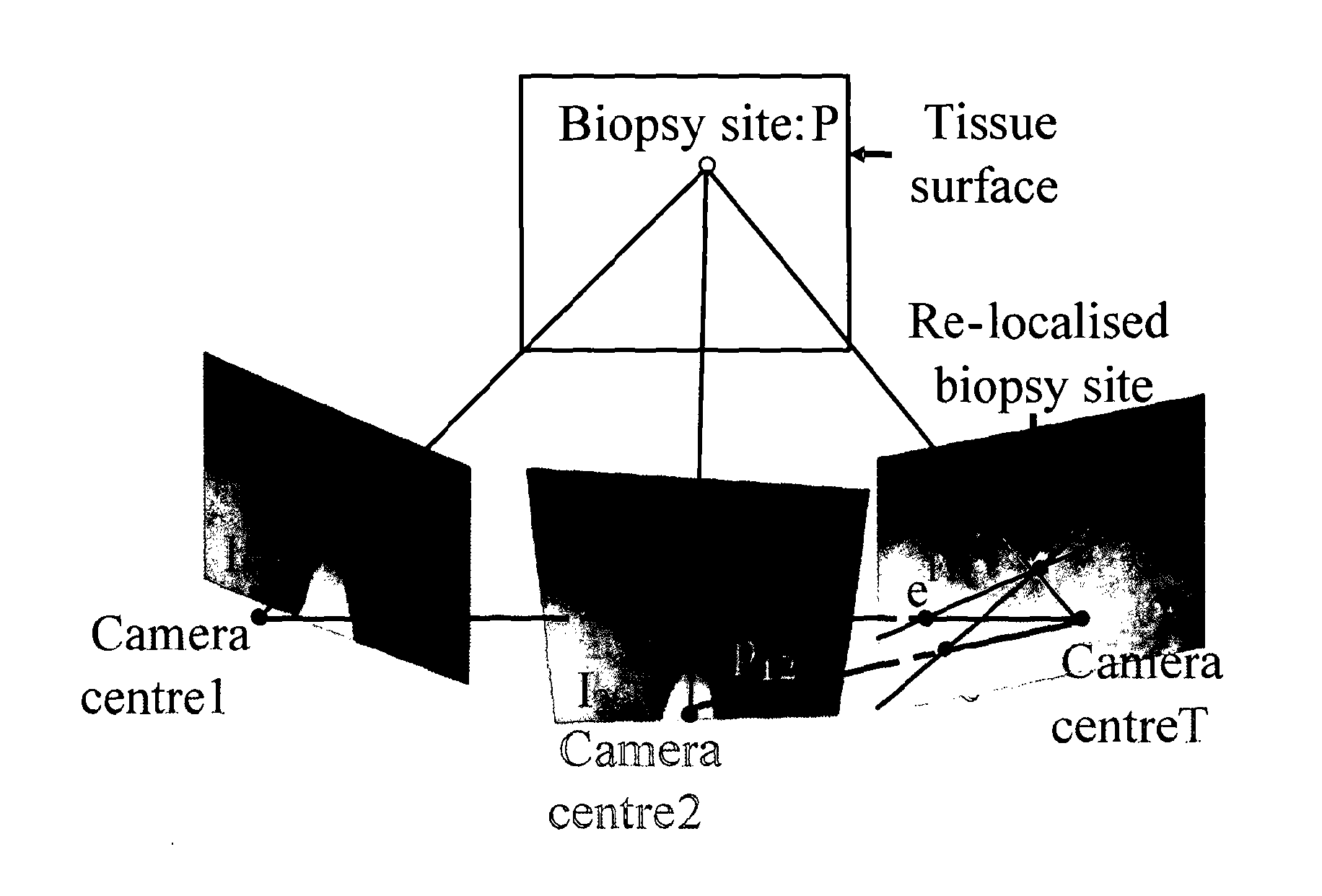
[0035]The following is a detailed description of an embodiment of the present invention as utilised in endoscopy. In particular, it is assumed that a site of interest has been acquired in two or more reference images, and the site now has to be identified (re-localized) in a target image. Note that the reference images and the target image may be acquired during the same clinical investigation (and therefore generally by the same imaging device associated with the endoscope). Alternatively, the reference images may have been acquired in a first clinical investigation and the target image is now acquired in a second clinical investigation at some later date. In this latter case, the imaging device used to acquire the target image may be the same as or different from the imaging device used to acquire the reference images. As described in more detail below, a positional sensor may be fitted at the tip of the endoscope in order to help re-localise biopsy sites when the endoscope camera...


PUM


Abstract

An apparatus and a computer-implemented method are provided for determining a location in a target image (T) of a site on a surface of a physical object using two or more reference images (I1, I2) of said physical object that have been obtained with a reference imaging device. Each of said two or more reference images includes said site on the surface of the physical object and was obtained with the reference imaging device having a different position and / or orientation relative to said physical object. The target image is obtained by a target imaging device and includes the site on the surface of the physical object. For each reference image, a set of feature mappings from the reference image to the target image is used to determine the epipolar geometry between the reference image and the target image, and a projection of the site from the reference image onto the target image is calculated from said epipolar geometry. The location in the target image of the site on the surface of the physical object is determined from the calculated epipolar projections for the two or more reference images.

Description

FIELD OF THE INVENTION [0001]The present invention relates to an apparatus and method for determining a location in a target image of a site on a surface of a physical object.BACKGROUND OF THE INVENTION[0002]Endoscopy is a minimally invasive procedure for the real-time acquisition of video images of the interior surfaces of an organ with a flexible or rigid endoscope. Endoscopy is often used to allow a biopsy to be taken. Significant problems for many endoscopies are biopsy site detection, path planning to reach the site, and re-localisation (re-identification) of the site during the same or a future examination. For example, many endoscopic procedures (such as oesophageal endoscopy for Barrett's Oesophagus) require the endoscopist to return to a location previously identified to take a measurement or extract a small sample of tissue (biopsy) for analysis of cellular structure and / or to detect the presence of pathology, in particular cancer and pre-cancerous conditions. Re-localisat...

Claims


Application Information

Patent Timeline
IPC IPC(8): G06K9/00G06V10/24
CPCG06K9/32G06T7/0042G06T7/0048G06T2207/30024G06T2207/10021G06T2207/10068G06T2207/10016G06T7/73G06T7/77G06V10/24
Inventor HU, MINGXINGALLAIN, BAPTISTEHAWKES, DAVIDOURSELIN, SEBASTIENLOVAT, LAURENCECOOK, RICHARD
Owner UCL BUSINESS PLC
Learn More