
Electronic device and light-guiding structure thereof

Active Publication Date: 2012-08-30
LITE ON ELECTRONICS (GUANGZHOU) LTD +1
View PDF10 Cites 0 Cited by
  • Summary
  • Abstract
  • Description
  • Claims
  • Application Information

AI Technical Summary

Benefits of technology

[0007]The present invention provides a light-guiding structure for the touch pad structure of an electronic device that is capable of achieving lower overall thickness and providing illumination around the touch pad structure thereof.
[0011]The present invention has the following advantages. The electronic device has the touch pad structure and the light-guiding structure. The light-guiding plate of the light-guiding structure has the thru-opening formed thereon for receiving the touch pad structure. Thereby, the overall thickness for the combination of the light-guiding structure and the touch pad structure can be reduced. In addition, the light-guiding plate has the light-guiding member formed around the thru-opening of the main body for illumination around the touch pad structure.

Problems solved by technology

However, by stacking the touch pad structure with an extra light-guiding plate, the thickness of the overall electronic device is undesirably increased.

Method used


Image

  • Electronic device and light-guiding structure thereof
  • Electronic device and light-guiding structure thereof
  • Electronic device and light-guiding structure thereof

Examples


Embodiment Construction

[0021]Before the present invention is described in greater detail in connection with the preferred embodiments, it should be noted that similar elements and structures are designated by like reference numerals throughout the entire disclosure.

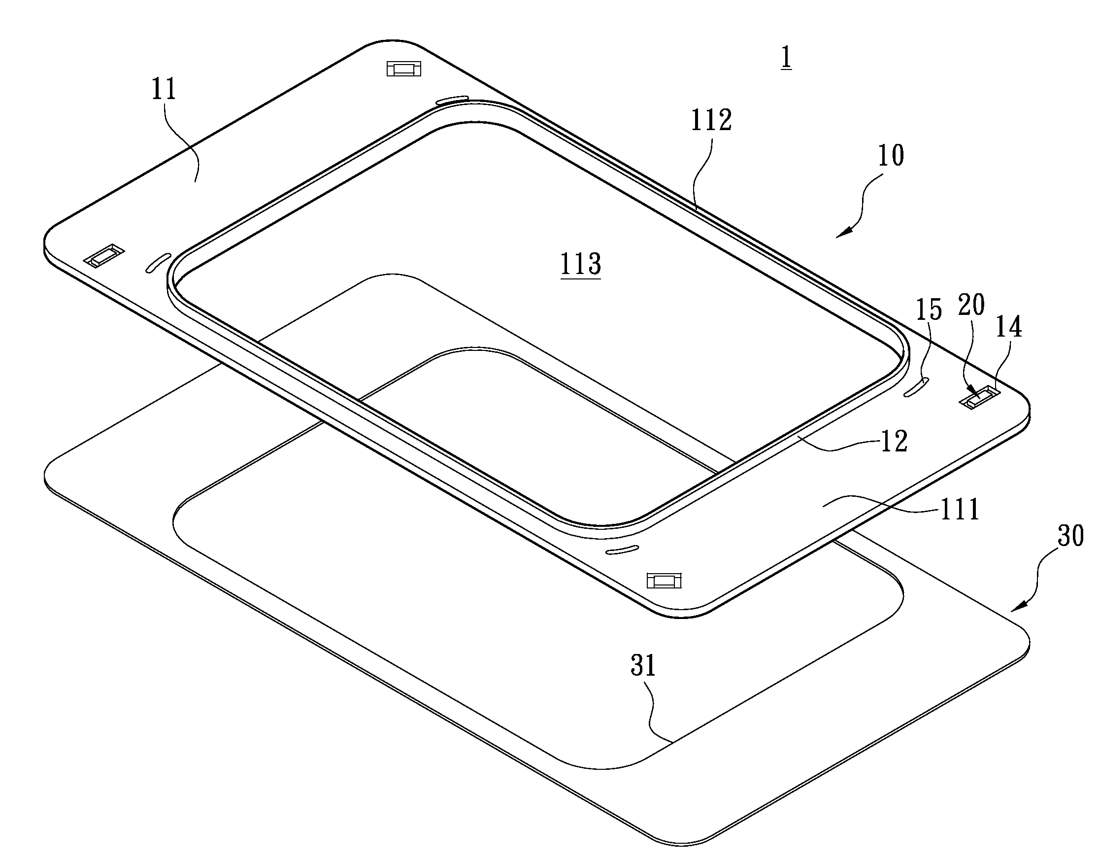
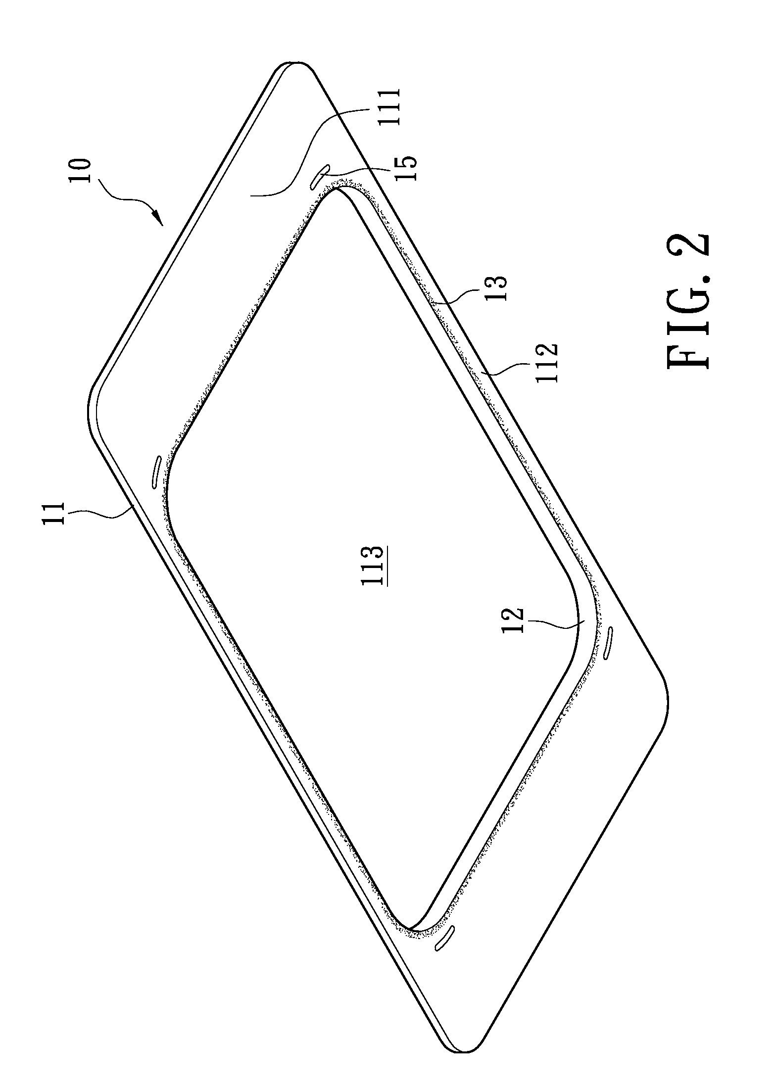
[0022]Please refer to FIGS. 1 to 3. The first preferred embodiment of a light-guiding structure 1 according to this invention is mounted on an electronic device 7 (as shown in FIG. 5). The light-guiding structure 1 comprises a light-guiding plate 10 and a plurality of light-emitting units 20.

[0023]The light-guiding plate 10 is made of light transmissive material and has a main body 11 having a thru-opening 113 formed thereon. The main body 11 has a pair of opposing first edge portions 111 and a pair of opposing second edge portions 112. The first edge portion 111 has a width W1, which is greater than the width W2 of the second edge portion 112. For this embodiment, the main body 11 and the thru-opening 113 are both round or angled rectangular s...


PUM


Abstract

An electronic device is disclosed, which includes a housing, a touch pad structure, and a light-guiding structure. The light-guiding structure includes a light-guiding plate and a plurality of light-emitting units. The light-guiding plate has a main body and a thru-opening formed on the main body. The main body has a pair of opposing first edge portions and a pair of opposing second edge portions. A light-guiding member is formed on the main body around the thru-opening. The light-emitting units are disposed on or beyond the light-guiding pate and around the light-guiding member and illuminate toward the first and second edge portions. The touch pad structure is received in the thru-opening and surrounded by the light-guiding member. The touch pad structure and the light-guiding member are exposed through a slot of the housing.

Description

BACKGROUND OF THE INVENTION[0001]1. Field of the Invention[0002]The present invention relates to an electronic device and a light-guiding structure thereof; more particularly, to an electronic device having a touch pad structure and a light-guiding structure thereof.[0003]2. Description of Related Art[0004]Nowadays, a variety of touch structures have been developed to provide human-machine interface in electronic devices, such as touch structure having a touch pad. A light-guiding structure has been applied to the electronic device to make the periphery of the touch pad structure illuminate.[0005]In a conventional light-guiding structure, a rectangular light-guiding plate is usually disposed under the touch pad structure. Light emitted by the corresponding light-emitting units is transmitted toward the light-guiding plate and creates illumination effect around the periphery of the touch pad structure. However, by stacking the touch pad structure with an extra light-guiding plate, th...

Claims


Application Information

Patent Timeline
IPC IPC(8): F21V8/00
CPCG06F1/169G06F1/1656
Inventor LIN, HUI-LINGWANG, CHIH-WEILO, SHIH-CHUNG
Owner LITE ON ELECTRONICS (GUANGZHOU) LTD
Learn More