Eureka AIR delivers breakthrough ideas for toughest innovation challenges, trusted by R&D personnel around the world.

Controlling latency and power consumption in a memory

a technology of memory and latency, applied in the field of data storage, can solve the problems of different access request delay, lower overall performance, and additional delay, and achieve the effect of improving system performance and increasing system latency

Active Publication Date: 2012-08-16
ARM LTD
View PDF4 Cites 11 Cited by
  • Summary
  • Abstract
  • Description
  • Claims
  • Application Information

AI Technical Summary

Benefits of technology

[0010]The present invention recognises that although one may need to increase the delay between accesses to a memory to reduce power consumption this has a detrimental effect on the latency of the system. However, it also recognises that it may be more important for the latency of the system that some access requests are not delayed while for others an additional delay may have a lower impact on overall performance. Thus, it provides different delays to the access requests in order to meet a required power consumption target in dependence on a priority of the access requests. In this way high priority requests are in general given a lower latency than low priority requests and the power consumption of the memory is reduced without a corresponding reduction in performance.
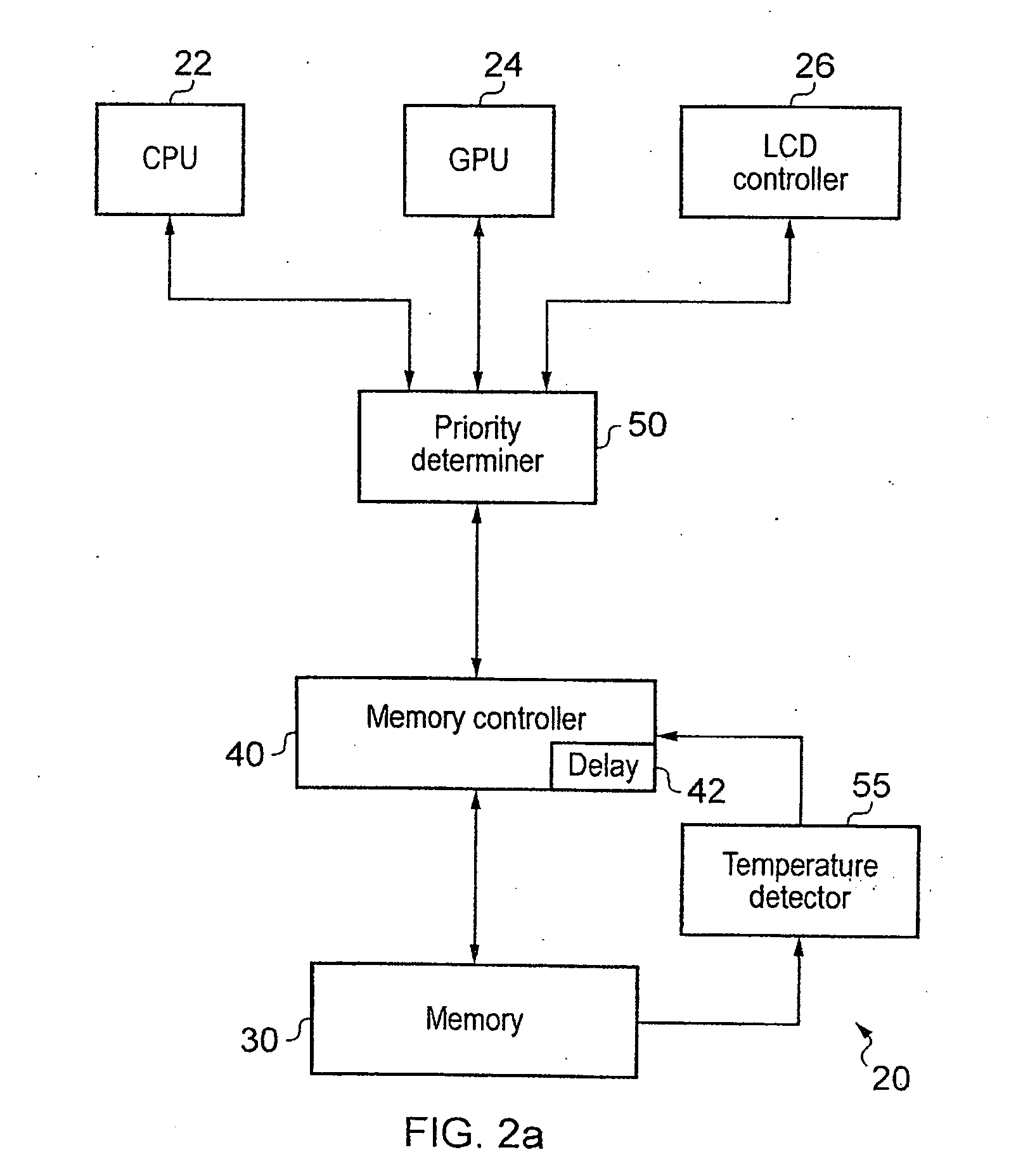
[0035]Where the power consumption is being controlled to control the temperature of the memory circuitry itself it may be advantageous if there is temperature detection circuitry associated with the memory that detects the temperature and sends a signal if it falls above or below a predetermined temperature. In this way, the power target can be varied in response to how the temperature actually varies and a predetermined average access delay can be directly varied to achieve a desired temperature operating range.

Problems solved by technology

However, it also recognises that it may be more important for the latency of the system that some access requests are not delayed while for others an additional delay may have a lower impact on overall performance.
Thus, it provides different delays to the access requests in order to meet a required power consumption target in dependence on a priority of the access requests.

Method used


Image

  • Controlling latency and power consumption in a memory
  • Controlling latency and power consumption in a memory
  • Controlling latency and power consumption in a memory

Examples


Embodiment Construction

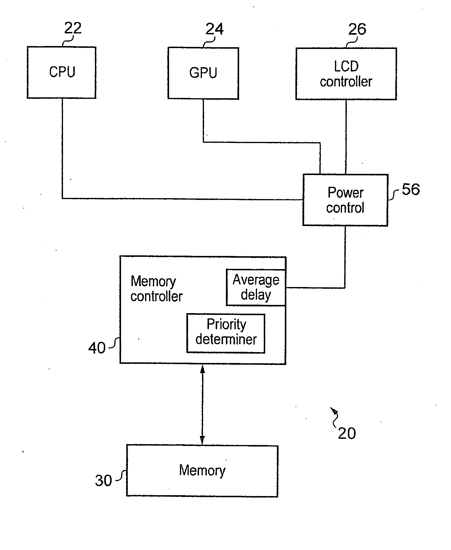
[0046]FIG. 2a shows a data processing apparatus 20 according to an embodiment of the present invention. Data processing apparatus 20 has number of devices for processing data. It has a central processing unit or CPU 22 a graphics processing unit GPU 24 and a LCD controller 26. This is purely an example and it should be clear to a skilled person that a processing apparatus having a number of different devices could fall within the scope of the present invention.

[0047]These devices all access memory 30 via memory controller 40. There is also a priority determiner 50 within data processing apparatus 20 that determines a priority of a transaction received from these devices. This priority determiner 50 may be associated with memory controller 40 or it may be independent of it and part of the processing apparatus. In the latter case it will be used for increasing the performance in general of the processing apparatus.

[0048]The priority determiner 50 assign a priority level which in this ...


PUM


Abstract

Memory circuitry, a data processing apparatus and a method of storing data are disclosed. The memory circuitry comprises: a memory for storing the data; and control circuitry for controlling power consumption of the memory by controlling a rate of access to the memory such that an average access delay between adjacent accesses is maintained at or above a predetermined value; wherein the control circuitry is configured to determine a priority of an access request to the memory and to maintain the average access delay at or above the predetermined value by delaying at least some accesses from access requests having a lower priority for longer than at least some accesses from access requests having a higher priority.

Description

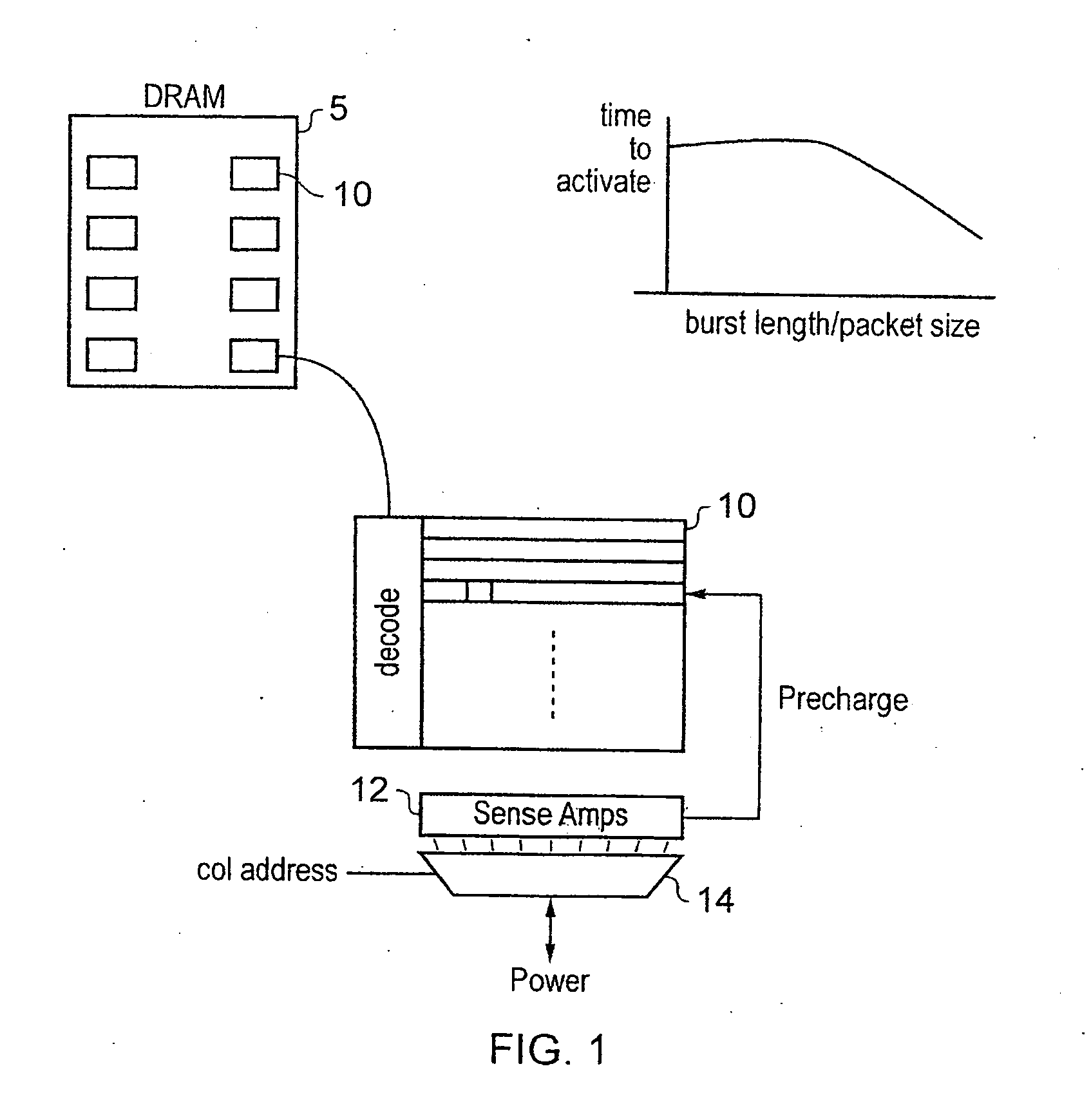
BACKGROUND OF THE INVENTION[0001]1. Field of the Invention[0002]The present invention relates to the field of data storage and in particular to controlling the latency and power consumption of a memory.[0003]2. Description of the Prior Art[0004]As memories such as DRAM increase in size and as they are mounted within systems in ever closer relation to each other and are on occasion stacked on top of each other, the power consumption of these memories may need to be controlled to avoid them overheating.[0005]With DRAM memories for example, there is significant power consumed when a line or row in the DRAM is activated. FIG. 1 shows an example of a conventional DRAM memory bank 5 consisting of 8 banks of memory 10. These memory banks are formed of arrays of data storage locations and an activation of a row in response to a row address in a data access will result in sense amplifiers 12 being fired and either the data that is stored in capacitors within the row being discharged onto the...

Claims


Application Information

Patent Timeline
IPC IPC(8): G06F12/00
CPCG06F13/1626G06F13/161G06F1/3225G06F1/3275G06F13/18
Inventor MACE, TIMOTHY CHARLESCRAWFORD, ASHLEY JOHN
Owner ARM LTD
Why Eureka
Eureka Blog
Learn More