Quick release spinal implant insertion device

Inactive Publication Date: 2012-08-02
TITAN SPINE
View PDF5 Cites 24 Cited by
  • Summary
  • Abstract
  • Description
  • Claims
  • Application Information

AI Technical Summary

Benefits of technology

[0012]A particular preferred sleeve of this invention has a partially circumferential, proximally stepped distal end configuration which provides plateaus, facets or steps with differing radial separation. The plateaus or steps mate with cooperating surfaces on intervertebral prostheses of differing vertical dimension or vertebral height and different geometries (i.e., the inserts are of different sizes and configurations) permitting a single inserter of this invention to be used with variously sized implants. This invention also utilizes a quick release holding feature, or structure which incorporates prongs and a preferred unique sleeve geometry. Together, these features provide stability to the implant-holder assembly, while maintaining a very slim profile.
[0015]Additionally, the instrument may be easily disassembled to assure proper cleaning, which can be a challenge with elaborate implant holder designs. Cleaning is important for operation of the device to prevent failures and to prevent infection.
[0016]This invention is an elegant spinal implant holder / dispenser that is straightforward and easy to use, yet accommodates a broad range of implant sizes and implant configurations. Providing the surgeon with a stable implant-inserter assembly significantly enhances the likelihood of success of the surgery.
[0018]Prior art includes threaded holding features, prongs, or a combination thereof. Threads can be time consuming to assemble / disassemble in the operating arena, and may become unstable if not threaded completely. Manipulation in a direction opposite the thread may cause the inserter to become unstable. Prongs provide some medial-lateral stability; however the size of the prongs may limit the compatibility with smaller devices, or if small enough to accommodate these sizes, may not provide sufficient stability to manipulate the implant intraoperatively. When designed large enough to provide stability, both threads and prongs can limit the design of the implant geometry.
[0020]The invention utilizes a quick release holding feature, which incorporate prongs and a novel distal end sleeve geometry. The sleeve geometry permits a single device of this invention to be used to implant intervertebral spinal fusion devices of various sizes, thereby reducing inventory, equipment and clean-up and storage costs. Together, these features, their combination and sub-combinations, provide stability to the implant-holder assembly, while maintaining a very slim profile. The device or tool also reduces inventory and surgical time by allowing use of single instrument to fully insert and manipulate cage. (Secondary instrument-tamp typically used).

Problems solved by technology

Spinal discs may be displaced or damaged due to trauma, disease or aging.
The extruded nucleus pulposus may press on the spinal nerve, which may result in nerve damage, pain, numbness, muscle weakness and paralysis.
Intervertebral discs may also deteriorate due to the normal aging process or disease.
As a disc dehydrates, the disc space height will be reduced leading to instability of the spine, decreased mobility and pain.
Collapse of the disc space can cause instability of the spine, abnormal joint mechanics, and premature development of arthritis or nerve damage, in addition to severe pain.
Unfortunately, the use of bone grafts presents several disadvantages.
Autografts, bone material surgically removed from the patient, can be undesirable because they may not yield a sufficient quantity of graft material.
The additional surgery to extract the autograft also increases the risk of infection and blood loss.
Furthermore, some patients complain that the graft harvesting surgery is more painful than the fusion surgery.
These conventional inserters suffer the drawback that holding structures may become disengaged during insertion or manipulation of the implant.

Method used


Image

  • Quick release spinal implant insertion device
  • Quick release spinal implant insertion device
  • Quick release spinal implant insertion device

Examples


Embodiment Construction

[0031]For the purposes of promoting an understanding of the principles of the invention, reference will now be made to the embodiments illustrated in the drawings (FIGS. 1-9D). It will nevertheless be understood that no limitation of the scope of the invention is thereby intended, such alterations and further modifications in the illustrated devices, and such further applications of the principles of the invention as illustrated therein being contemplated as would normally occur to one skilled in the art to which the invention relates.

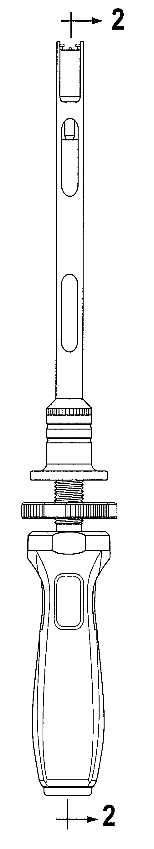
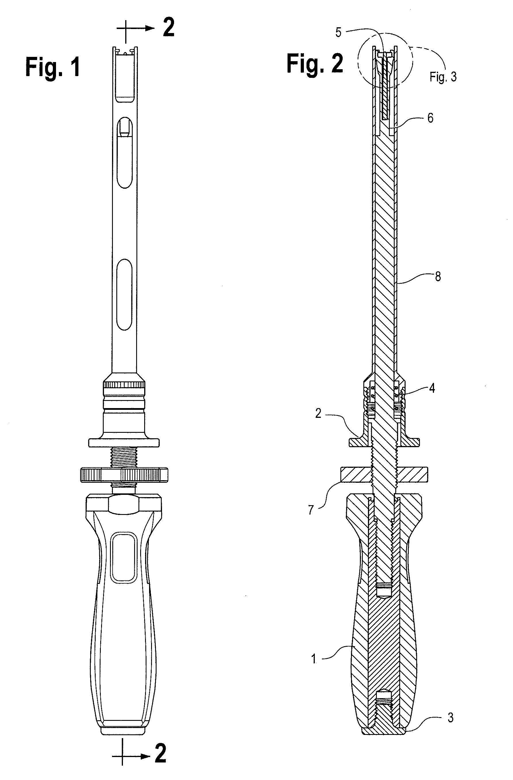
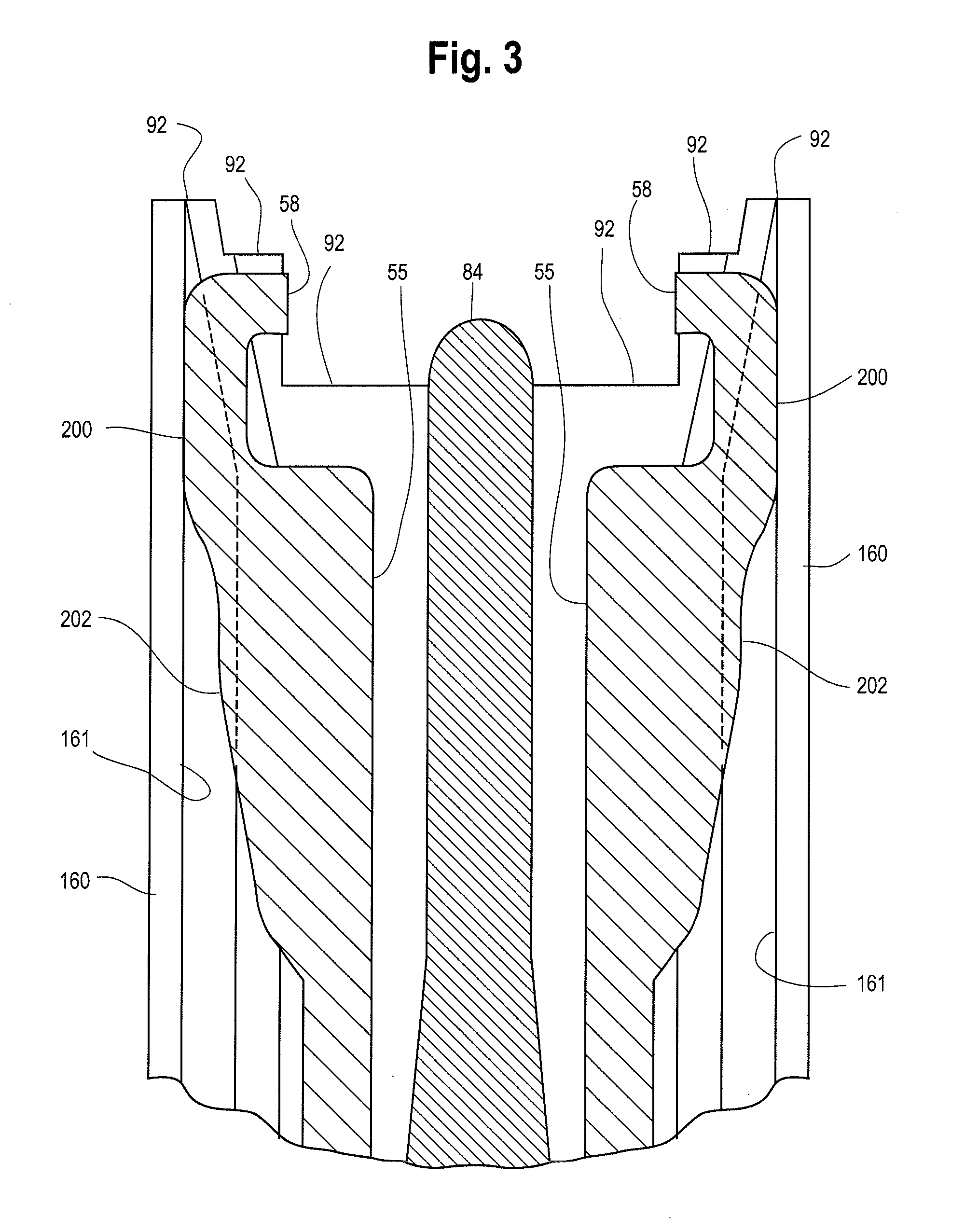
[0032]The implant holder of this invention is a simple but elegant holder / implant-direction device that includes a spring-loaded mechanism, which urges the collar distally to close the prongs, which capture the implant when closed and a central locating pin that allows the medical professional to guide the implant itself onto the holder. The holder can be disassembled for ease of cleaning and quickly reassembled for use. The holder utilizes a very simp...


PUM


Abstract

This invention is a novel, quick release spinal implant inserter, insertion device or holder / dispenser. It has the advantage of providing enhanced surgeon control of the prosthesis insertion process including the ability to insert and manipulate intervertebral spinal fusion implants or devices of many different sizes.

Description

BACKGROUND OF THE INVENTION[0001]Intervertebral discs, located between the endplates of adjacent vertebrae, stabilize the spine, distribute forces between vertebrae and cushion vertebral bodies. A normal intervertebral disc includes a semi-gelatinous component, the nucleus pulposus, which is surrounded and confined by an outer, fibrous ring called the annulus fibrosis. In a healthy, undamaged spine, the annulus fibrosis prevents the nucleus pulposus from protruding outside the disc space.[0002]Spinal discs may be displaced or damaged due to trauma, disease or aging. Disruption of the annulus fibrosis allows the nucleus pulposus to protrude into the vertebral canal, a condition commonly referred to as a herniated or ruptured disc. The extruded nucleus pulposus may press on the spinal nerve, which may result in nerve damage, pain, numbness, muscle weakness and paralysis. Intervertebral discs may also deteriorate due to the normal aging process or disease. As a disc dehydrates, the dis...

Claims


Application Information

Patent Timeline
IPC IPC(8): A61B17/88
CPCA61F2/4611A61F2/4465A61F2002/2835A61F2002/30616A61F2002/4629A61F2002/30785A61F2002/4475A61F2002/4628A61F2002/30777A61F2002/30593
Inventor LEZAMA, ALEJANDROSCHNEIDER, JENNIFER M.
Owner TITAN SPINE
Why Eureka
Try Eureka