
In-line color mixer

a color mixer and mixer technology, applied in the field of polymeric materials, can solve the problems of time-consuming discontinuous process, difficult to handle, inconsistent color distribution, etc., and achieve the effect of minimal cleaning, rapid color change, and minimal cleaning

Inactive Publication Date: 2012-08-02
REDUCTION ENG +1
View PDF3 Cites 2 Cited by
  • Summary
  • Abstract
  • Description
  • Claims
  • Application Information

AI Technical Summary

Benefits of technology

[0026]In step (d), liquid formulation is suitably sprayed directly at the powder, suitably avoiding as far as possible, contacting a wall which defines a mixing chamber of the mixer. Preferably, droplets of liquid formulation are sprayed. Suitably, a spray device is used in step (d). It may comprise an atomizing spray device arranged to atomize the liquid formulation, an atomizer, vaporizer, mister, sprinkler, nebulizer, or any other suitable liquid dispenser. In order to facilitate substantially homogenous mixing of liquid formulation and powder (while avoiding clumping of colorant and / or other functional additive and avoiding overly concentrated regions of colorant and / or other functional additive) the spraying in step (d) is suitably carried out at relatively low pressure. For example, the spray device may be arranged to atomize the liquid formulation using less than 50 psi, preferably less than 35 psi, more preferably less than 25 psi, especially less than 15 psi of pressure. This may produce a softer application of the liquid formulation to the powder and may avoid the formulation being jetted through a mass of powder thereby contacting the walls of the mixing chamber. If liquid formulation is allowed to build up on walls of the mixing chamber, there is a tendency for occasional highly concentrated regions of color or functional additives to develop within the powder which is undesirable.
[0050]Advantageously, the apparatus may allow color changes to be undertaken rapidly with minimal cleaning, since the pulverizer contains uncolored powder in use and the first and second combinations may be selected according to the desired color for the powder.

Problems solved by technology

However, such solid materials can be difficult to handle and can mix unevenly with the polymeric material powder leading to inconsistent color distribution in the final molded product.
Also, such a process is a time-consuming discontinuous process.
However, there are also problems associated with use of such formulations.
However, disadvantageously, this necessitates extensive and prolonged cleaning of the pulverization apparatus should it be desired to change the color of the polymeric material powder to be produced.
This is generally uneconomic.
Furthermore, it is challenging to homogenously color the polymeric material.
If liquid formulation is allowed to build up on walls of the mixing chamber, there is a tendency for occasional highly concentrated regions of color or functional additives to develop within the powder which is undesirable.

Method used


Image

  • In-line color mixer
  • In-line color mixer
  • In-line color mixer

Examples


Embodiment Construction

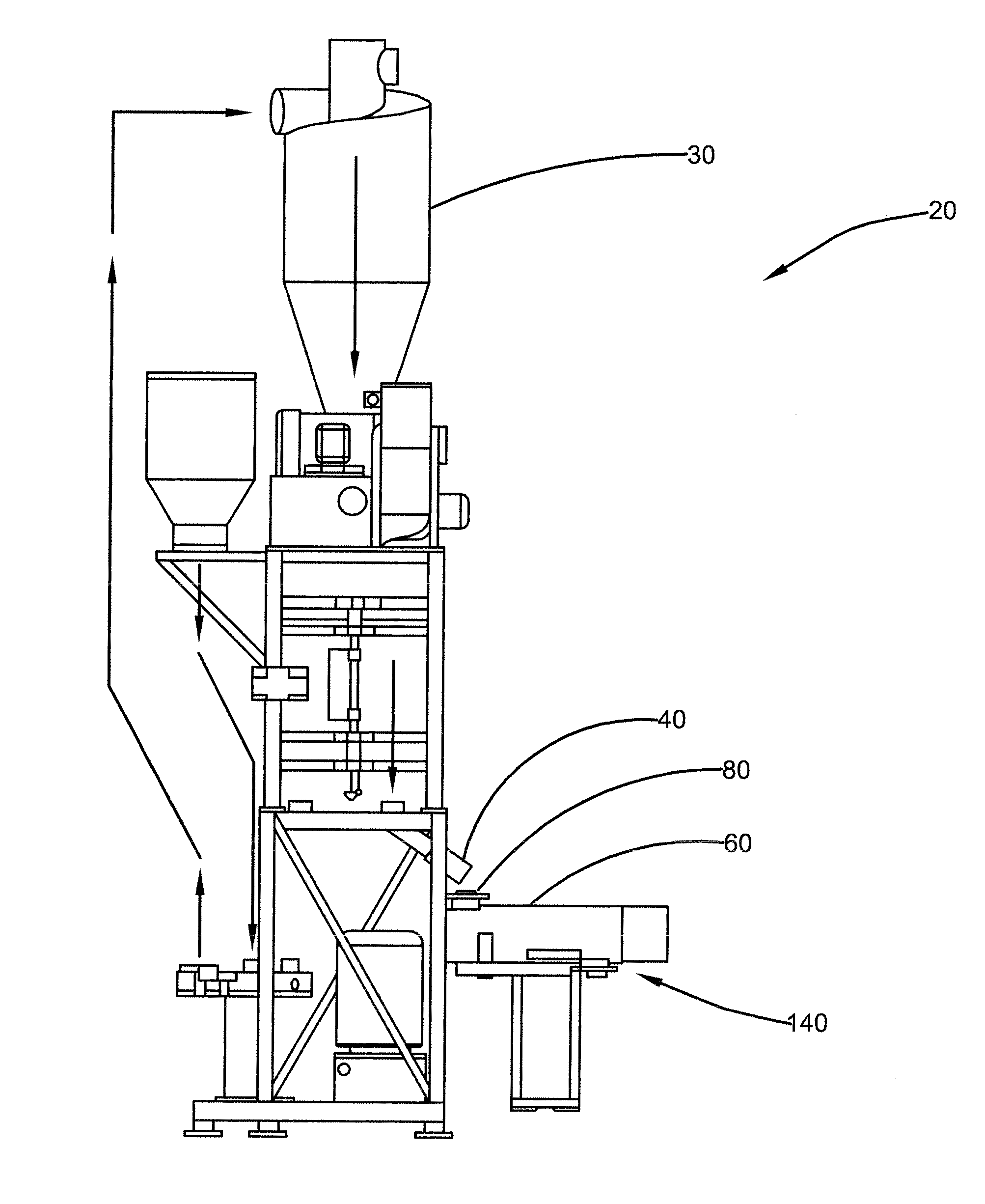
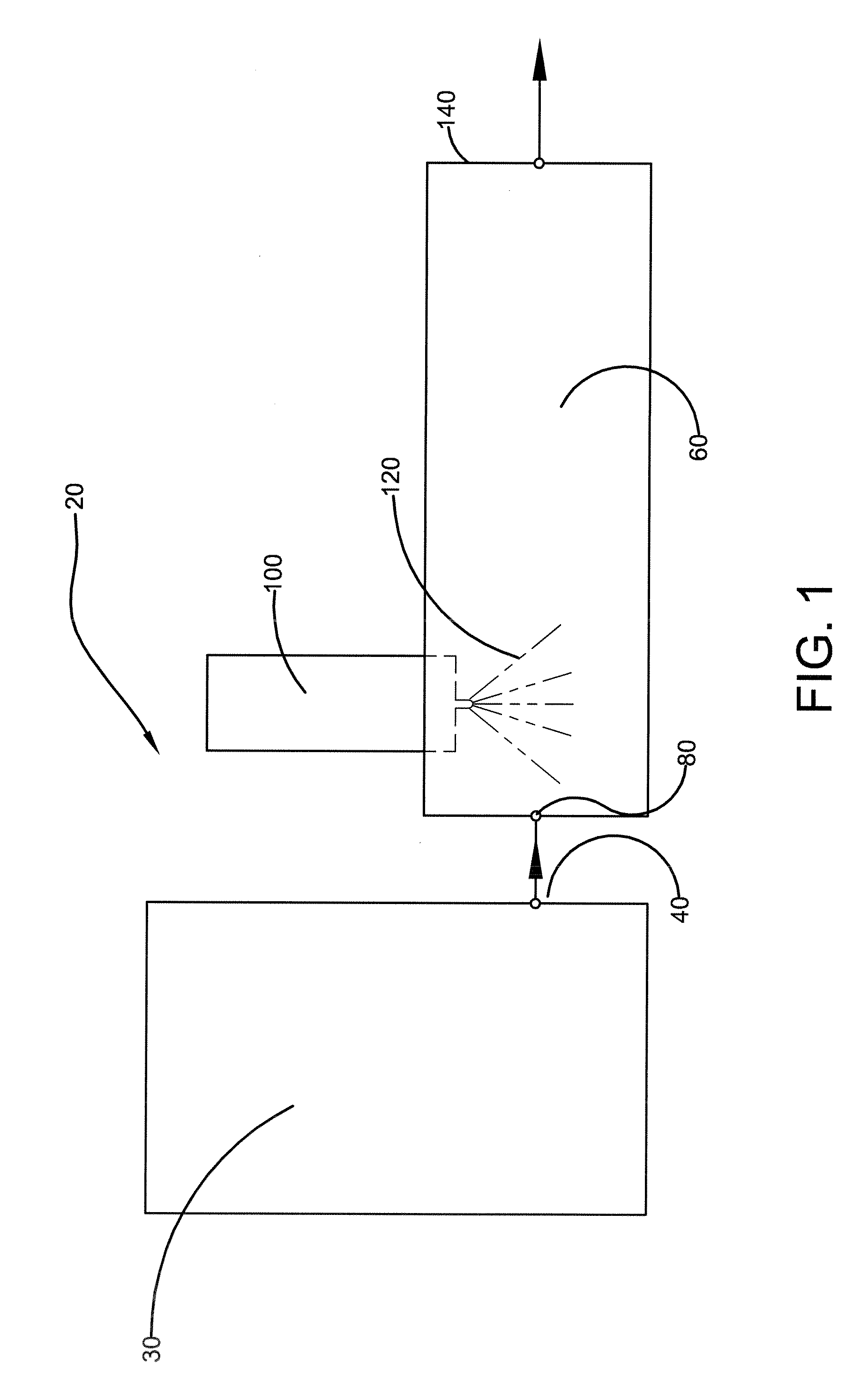
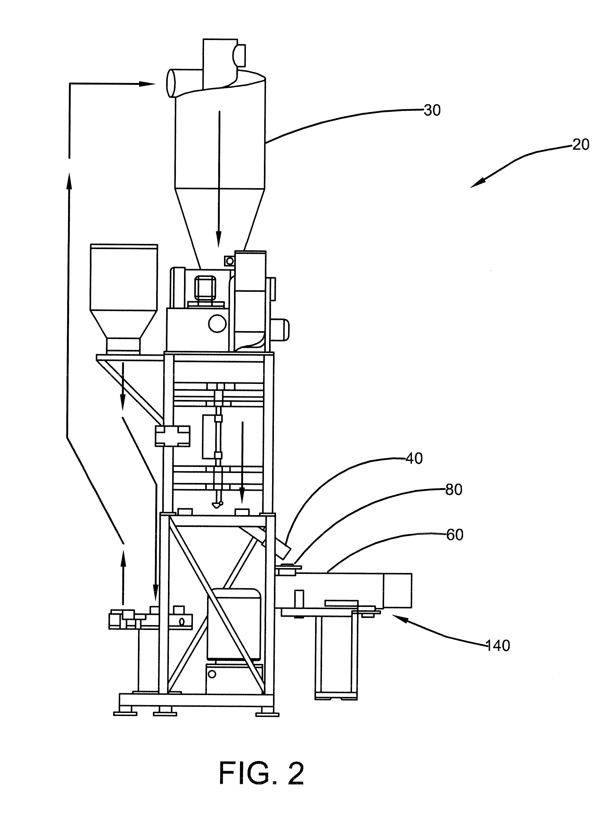
[0067]Referring now to the drawings wherein the showings are for purposes of illustrating embodiments of the invention only and not for purposes of limiting the same, and wherein like reference numerals are understood to refer to like components, FIGS. 1-10 show an apparatus 20 including a pulverizer 30 which is arranged to deliver uncolored pulverized polymer powder via its outlet 40 directly into a mixer 60 via its inlet 80. A spray device 100 is operatively connected to the mixer 60 and is arranged to produce a spray 120 of a colored liquid formulation which is directed at the pulverized polymer powder thereby to color the powder. The powder and liquid formulation are mixed resulting in an evenly colored powder passing from an outlet 140 of the mixer, after which the colored powder may be stored for subsequent use in rotational molding. Further details on the apparatus are provided below.

[0068]The pulverizer 30 may be of conventional design. It is arranged to receive pelletized p...


PUM

PropertyMeasurementUnit
temperatureaaaaaaaaaa

Abstract

The method of producing a colored powder of a polymeric material includes the steps of selecting a feedstock of said polymeric material, pulverizing said polymeric material in a pulverizer to produce a powder, moving the powder directly from the pulverizer to a mixer; spraying a liquid formulation including a colorant into the powder within the mixer, and mixing the liquid formulation and powder.

Description

CROSS-REFERENCE TO RELATED APPLICATIONS[0001]This application claims the benefit of U.S. Provisional Application No. 61 / 432,777, titled IN-LINE COLOR MIXER, filed Jan. 14, 2011, which is herein incorporated by reference.I. BACKGROUND[0002]A. Field of Invention[0003]This invention relates generally to a polymeric material, and more specifically to coloring of a powderous polymeric material for use in making components by melt-processing, for example by rotational molding.[0004]Rotational molding is used for the production of hollow containers and other products of large size and complicated structure which cannot be readily molded by other conventional molding techniques such as injection molding and sheet thermoforming. Such structures include, for example, gasoline tanks, casks, storage tanks and toys.[0005]Rotational molding includes the steps of feeding a powder comprising polymeric material to a mold, heating the mold from the exterior while rotating the mold and melting the pow...

Claims


Application Information

Patent Timeline
Patent Type & Authority Applications(United States)
IPC IPC(8): B02C19/00B01F23/70
CPCB01F3/1221B01F7/00158B01F7/022B01F7/04B01F15/00032B02C23/20B29B7/94B01F3/2071B01F2215/005B02C19/00B29B7/44B01F23/53B01F27/071B01F27/0726B01F27/62B01F27/70B01F35/1453B02C19/0056B01F23/71B01F2101/30
Inventor SLY, ROBERTMAURI, JIMMASAR, JEFFBELL, KEITH
Owner REDUCTION ENG
Learn More