
Method and device for controlling the temperature of steam in a boiler

a technology for controlling the temperature of steam in a boiler and steam, which is applied in the direction of flush cleaning, lighting and heating apparatus, and cleaning using liquids. it can solve the problems of changing the heat transfer and steam temperature, the boiler gradually becomes fouled, and the damage to the mechanical system. it achieves the effect of improving the steam temperature control

Inactive Publication Date: 2013-08-01
SIEMENS AG
View PDF7 Cites 2 Cited by
  • Summary
  • Abstract
  • Description
  • Claims
  • Application Information

AI Technical Summary

Benefits of technology

This patent describes a new method for controlling the heat balance of a boiler by using fouling on the heat exchanger surfaces. With the help of sootblower devices, the temperature of the boiler can be regulated by controlling the heat transfer at the surfaces. This method allows for better control over the thermal characteristics of the boiler, resulting in improved efficiency and cost savings. The overall heat balance of the boiler is optimized by cleaning evaporator and superheater surfaces to ensure minimal cleaning of individual boiler regions. The method also includes a short average operating time for a heat exchanger if it is clean after its last cleaning operation.

Problems solved by technology

Said depositions firstly reduce the heat transfer, secondly block the exhaust-gas path, and not least can form conglomerates which are so large that, if they at some time become detached from their support, they can cause considerable mechanical damage as they fall owing to their compact mass and high falling speed.
After all cleaning measures have ended, the boiler gradually becomes fouled again, which in turn correspondingly changes the heat transfer and the steam temperatures.
Here, however, the fouling and the resulting thermal losses can be measured only with difficulty.
The large differences in the fouling before and after the sootblowing of the individual boiler regions and the progressively increasing fouling can disrupt the sensitive balance of the heat distribution, and constitute a significant impediment with regard to the thermal regulability of the boiler.
So-called “thermal imbalances” arise when temperature differences arise in tracts of the heat exchanger which are merged again after the splitting-up of the steam quantities.
The temperature differences arise owing to non-uniform splitting-up and non-uniform heat transfers caused by differences in the flue gas flow and temperature.
It has also been found that fouling of upstream heat exchangers leads to increased heat absorption in the downstream heat exchangers, and thus represents only a small fraction of an increased waste-gas loss of the boiler.
Here, however, by injection of water into the fresh steam, in principle only cooling can be effected, and only a limited injection quantity can be used.
Owing to fouling, the distribution of the heat transfer between the evaporator and superheater can be displaced to such an extent that firstly the existing injection capacity is no longer sufficient to keep the steam temperature below a desired or safety-related value.
Secondly, a situation may arise in which the steam, even in the case of closed injection, no longer reaches the required temperature value.
Individual heat exchangers without downstream injection-cooling arrangements, such as evaporator regions and final superheaters, however cannot be thermally balanced.
Where no pivoting burner device or flue gas recirculation is used, the fresh steam evaporation can be held in the control range only with selective stratified firing, which is not always successful.
It is however scarcely possible in this way to adequately control the reheater injection rate.
Thermal imbalances which arise are compensated for by corresponding safety margins; here, the optimum temperatures are, on average, undershot, which leads in part to an increased heat demand of the process, or reduces the hot steam injection required for controlling the steam temperature to zero.
In summary, it can be stated that thermal regulability of the boiler, with the aim of stable and optimum thermal conditions of the boiler, based solely on the firing and punctiform injection cooling is highly cumbersome and complex.
It is a disadvantage in particular that thermal imbalances can always arise.
Additional problems arise owing to the fouling in the boiler region, which always influences the heat transfers at the heat exchanger pipes and is negatively superposed on the regulation process.

Method used


Image

  • Method and device for controlling the temperature of steam in a boiler
  • Method and device for controlling the temperature of steam in a boiler
  • Method and device for controlling the temperature of steam in a boiler

Examples


Embodiment Construction

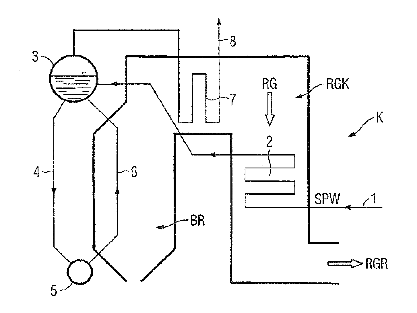
[0043]FIG. 1 illustrates, in highly simplified form, a steam generator. In the combustion chamber BR of the boiler K, a solid fossil fuel, for example carbon dust, is burned. The flue gas RG generated in the process is conducted through the flue gas duct RGK to the flue gas cleaning arrangement RGR. The evaporation of supplied feed water SPW takes place in the pipe systems of the evaporator chamber and of the heat exchanger. The system is conventionally constructed such that feed water is supplied from the feed water tank 1 to the feed water preheater 2 (ECO). From there, the water-steam mixture passes into the drum 3 and is supplied via the downpipes 4, the distributor collector 5 and the ascending pipes 6 to the superheater (7 or Ü) and subsequently to the turbine 8. The superheater Ü may furthermore also comprise a reheater ZÜ.

[0044]According to the invention on which this application is based, the steam temperature is controlled and regulated by virtue of a certain fouling of th...


PUM


Abstract

A method and a corresponding device for controlling the temperature of steam in a boiler of a steam generator are provided. The gradual accumulation of dirt on heat exchanger surfaces inside the boiler is incrementally regulated by soot blowers. The targeted influencing of the heat transfer on the heat exchanger surfaces enables the steam temperatures to be controlled and regulated.

Description

CROSS REFERENCE TO RELATED APPLICATIONS [0001]This application is the US National Stage of International Application No. PCT / EP2011 / 056853 filed Apr. 29, 2011 and claims the benefit thereof. The International Application claims the benefits of German application No. 10 2010 018 717.8 filed Apr. 29, 2010, both of the applications are incorporated by reference herein in their entirety.FIELD OF THE INVENTION [0002]The invention relates to a method for controlling the temperature of steam in a boiler, and to a corresponding device.BACKGROUND OF THE INVENTION [0003]A fossil-fired steam generator or boiler of a power plant is generally composed of a combustion chamber, an evaporator chamber and a system of heat exchangers which are connected to the evaporator chamber. There are numerous different embodiments of the boiler structures, such as for example drum-type boilers or Benson boilers. In one variant, the evaporator chamber is composed of a pipe arrangement which is in direct thermal ...

Claims


Application Information

Patent Timeline
IPC IPC(8): F28G15/00F22B35/00F28G9/00
CPCF22B35/00F22B37/56F28G1/16F28G15/003F28G9/00Y10T137/0419
Inventor HERTWECK, KARLHEINZ
Owner SIEMENS AG
Learn More