
Method of cutting out part with making partially welded spots in wire-cut electrical discharge machining

a technology of electrical discharge machining and wire cutting, which is applied in the direction of electrical-based machining electrodes, manufacturing tools, electric circuits, etc., can solve the problems of workpieces that cannot be attracted magnetically or workpieces, workpieces that cannot be processed on the surface, and adverse possibilities, so as to shorten the total machining time and improve machining efficiency. , the effect of easy breakag

Active Publication Date: 2012-08-02
WEST ELECTRIC CO LTD
View PDF7 Cites 31 Cited by
  • Summary
  • Abstract
  • Description
  • Claims
  • Application Information

AI Technical Summary

Benefits of technology

[0016]With the method of cutting out a part with making partially welded spots in wire electrical discharge machining of the present invention, there is no need of cutting anew in the uncut spot left in the cutting path or kerf as in the conventional process and therefore the completely cut-out part or product is made easily in a single discharge machining operation. The welded spot to keep the cut-out part together with the workpiece is not as tough as stock workpiece material, but so vulnerable or fragile as to be easily broken by any weak external impact to completely cut off the part or product away from the workpiece. The method of the present invention as stated earlier, because of having no necessity of cutting anew the uncut spot again with electrical discharge machining, makes it possible to shorten the totality of machining time, thereby improving the machining efficiency. Further, the method of the present invention is effective to prevent the part or product from tilting and / or falling, which would cause damages to the part and / or workpiece.
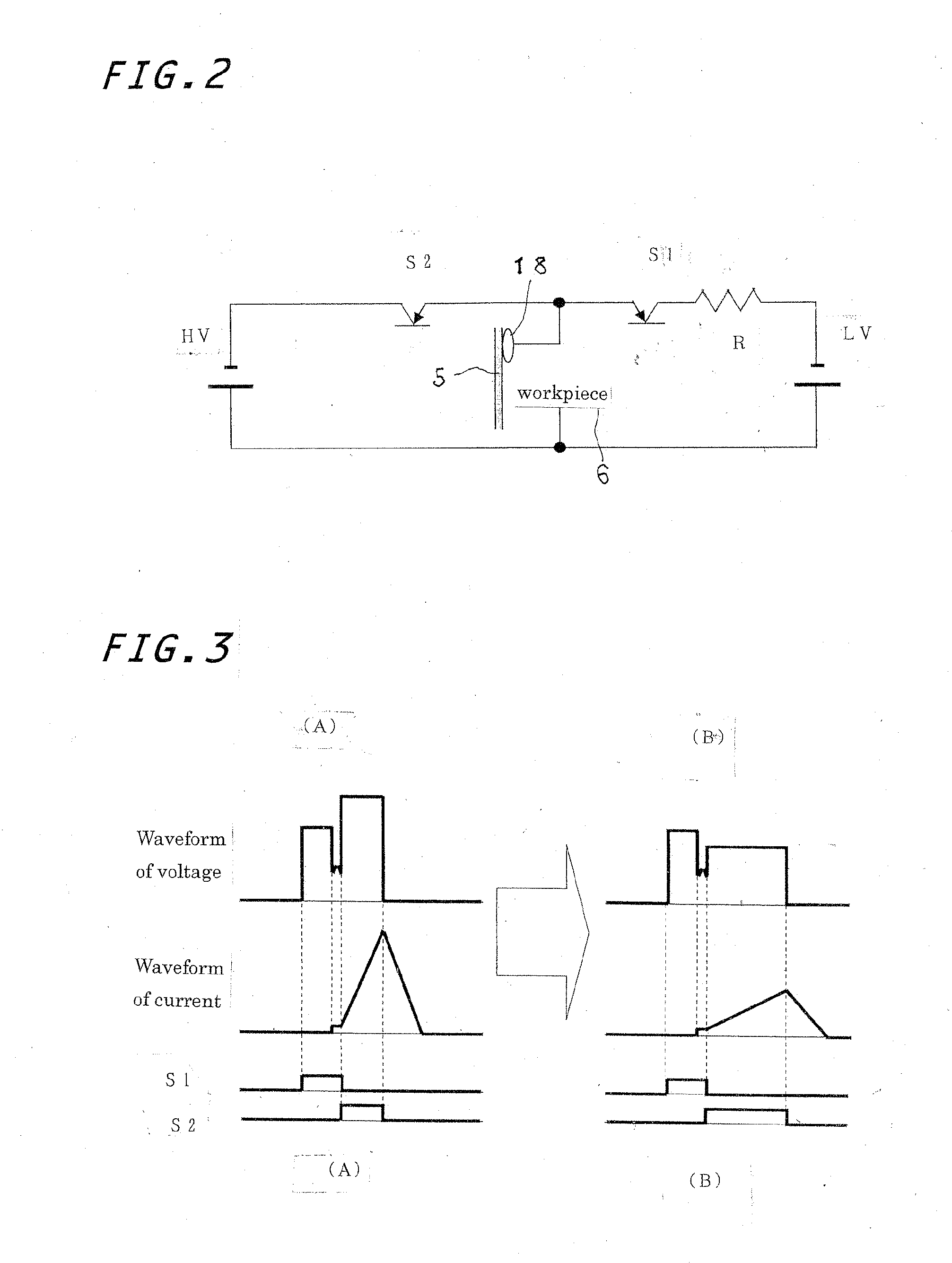
[0017]Meanwhile, the electrical discharge phenomenon of a qualitatively long interval causing a breakdown between the metal electrodes lying in a gaseous insulator and the breakdown starts with a corona discharge phase, then going through a spark discharge phase and an arc discharge phase in sequence, and ends in the breakdown. With the electrical discharge machining on the workpiece, moreover, the discharge cutting of the workpiece is carried out by ending the current supply at the timing of spark discharge. With the welding phase in the machining process of the present invention to make coalescent spot or welded spot in the cutting path, the cut-out part is welded with the workpiece with the arc welding at an arc discharge range, following the discharge machining of the workpiece at a spark discharge range. The wire electrode under the arc discharging cutting is fused partially around the periphery thereof to provide filler material. Thus, the workpiece is machined with electrical discharge along the cutting path of the wire electrode in parallel with the feed direction of the wire electrode and the part cut just before with the discharge machining is welded with the filler material by sequential arc discharge whereby the cut-out part is welded together with the workpiece.

Problems solved by technology

When leaving intact the uncut spots in return for isolation of the part, there is a risk that the part going to be cut out from the workpiece gets tilted relative to the clamped workpiece shortly before the end of machining process, whereby the short circuit occurs between the wire electrode and the workpiece, causing an interruption of electrical discharge and / or an abnormal discharge, which would cause damages to the processed surface of the workpiece.
When completely cutting out the part from the workpiece, there would be an adverse possibility that the workpiece couldn't be attracted magnetically or the workpiece, even though attractable magnetically, is too heavy in weight to be supported with any practical magnetic force.

Method used


Image

  • Method of cutting out part with making partially welded spots in wire-cut electrical discharge machining
  • Method of cutting out part with making partially welded spots in wire-cut electrical discharge machining
  • Method of cutting out part with making partially welded spots in wire-cut electrical discharge machining

Examples


Embodiment Construction

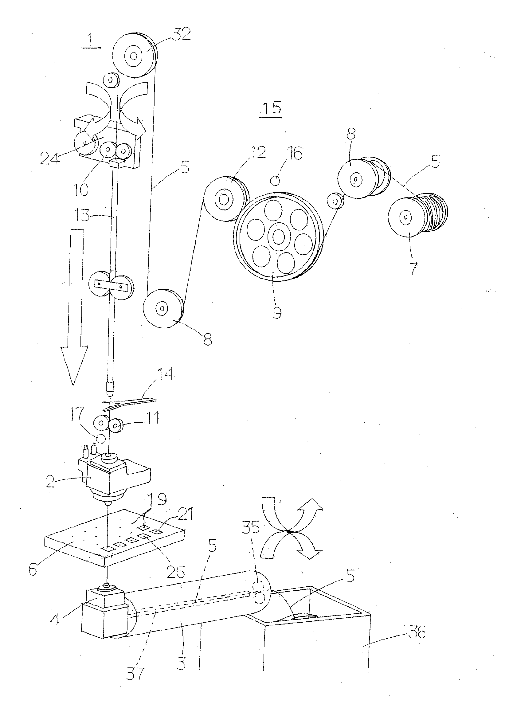
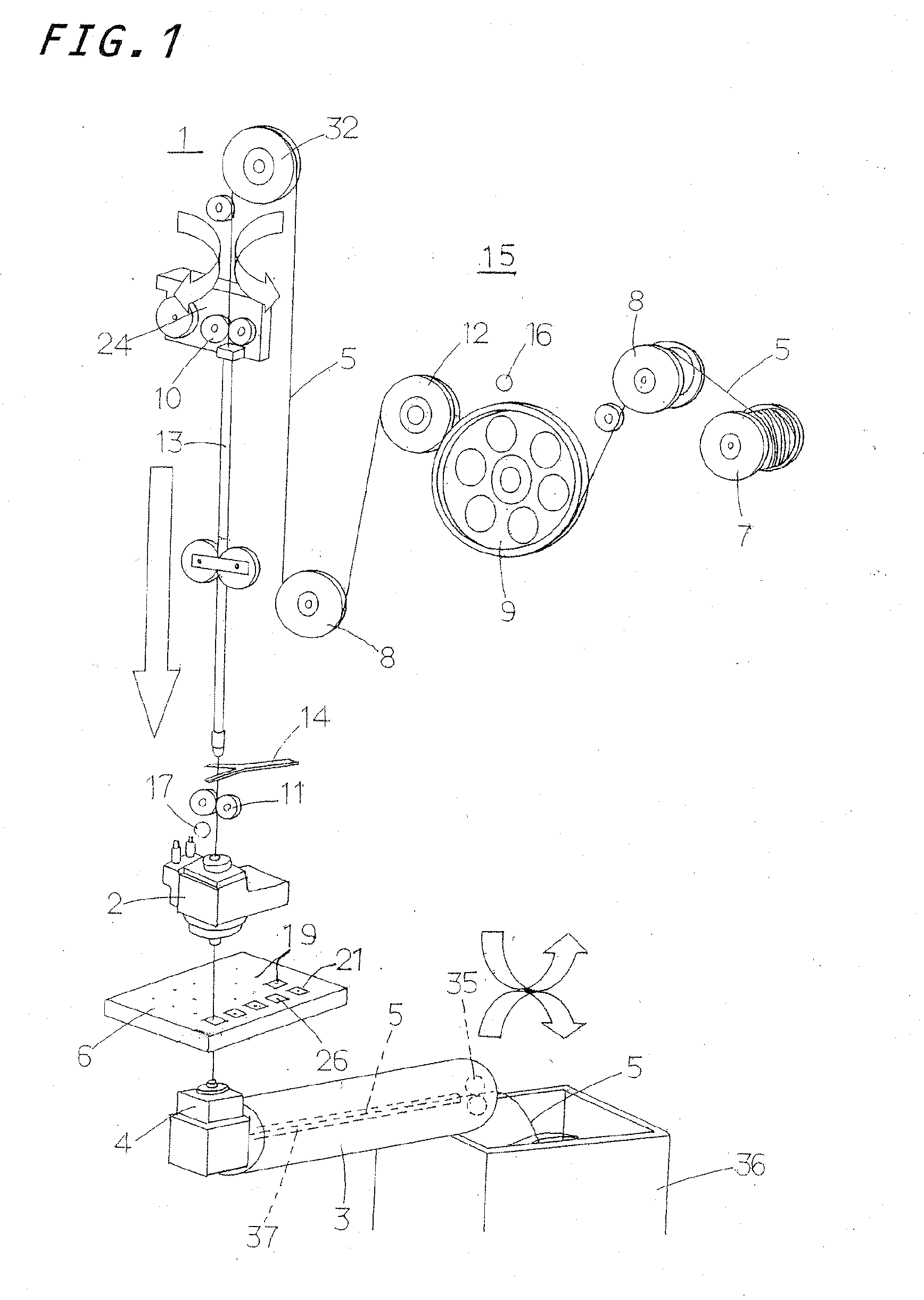
[0027]A method of cutting out a part with making welded spots in wire electrical discharge machining according to the present invention is befitted to use in a wire electrical discharge processor to cut out a part with making the welded spots to keep the cut-out part against falling away apart from a workpiece by spark discharge energy occurring when the processing potential is applied across a wire electrode and the workpiece. A preferred embodiment of the wire electrical discharge processor to carry out the method of cutting the part with making welded spots in wire electrical discharge machining according to the present invention will be hereinafter described in detail with reference to FIG. 1. The wire-cut electrical discharge processor is generally composed of a source bobbin 7 mounted on a machine frame 15 and having wire electrode coils 5 wound around the bobbin 7, change-of-direction rollers 8 to control threading directions of the wire electrode 5 unwound out of the bobbin ...


PUM

PropertyMeasurementUnit
lengthaaaaaaaaaa
voltageaaaaaaaaaa
voltageaaaaaaaaaa

Abstract

A method of cutting out a part from a workpiece with making partially welded spots in wire electrical discharge machining to keep the part against falling apart away from the workpiece. There is no need to cut anew the welded spot left as in the conventional process. The cut-out parts are cut off at a time after breakage of the welded spots caused by an external impact. The electric processing condition applied across an inter-electrode space between the wire electrode and the workpiece is changed from a cutting phase to a welding phase in which the wire electrode is fused partially at some spots along a cutting path of a predetermined contour on the workpiece to weld together the cut-out part and the workpiece at the fused spot on the wire electrode.

Description

FIELD OF TEE INVENTION[0001]The present invention relates generally to a wire electrical discharge machining to cut out a part or product from workpiece of strips, plates or sheets by spark discharge energy occurring when a gap voltage is applied across a wire electrode and a workpiece, and, more particularly, this invention relates to a method of producing the part with making partially welded spots integral with the workpiece in electrical discharge machining to keep the machined parts or products against falling away from the workpiece.BACKGROUND OF THE INVENTION[0002]In conventional wire-cut electrical discharge processors in which a part or product is cut off by spark discharges occurring between a wire electrode and a workpiece of cemented carbide, hardened steel and so on, a wire electrode before the onset of electrical discharge is threaded through a starting hole pierced in advance in the cut-out part or workpiece and, while wire electrical discharge machining is being done...

Claims


Application Information

Patent Timeline
Patent Type & Authority Applications(United States)
IPC IPC(8): B23H7/10B23H1/00
CPCB23H7/04B23K9/007B23H7/06B23H7/02B23H7/18B23H9/00
Inventor MITSUYASU, TAKASHI
Owner WEST ELECTRIC CO LTD
Learn More