Hybrid component and method for manufacturing a hybrid component

Active Publication Date: 2012-08-02
DAIMLER AG
View PDF3 Cites 5 Cited by
  • Summary
  • Abstract
  • Description
  • Claims
  • Application Information

AI Technical Summary

Benefits of technology

[0004]Exemplary embodiments of the present invention are directed to developing a hybrid component and a method for manufacturing a hybrid component of the type referred to above, so that a deformation of the hybrid component can be detected in a simple way.
[0031]The hybrid component according to the invention monitors its own condition in a quasi-active manner, and any deviation from the desired condition, for example caused by damage owing to excessive loading, is indicated by a signal. Such deviations, which may also be caused by other changes in rigidity, allow unambiguous conclusions with respect to the quality of the component and thus to its behavior in a crash. The signals emitted by the hybrid component are acquired, stored and evaluated, so that they can have a positive influence on any subsequent further development of the hybrid component. It is possible, for example, to record the local frequency of damage and to interpret these facts suitably when redesigning the component. In addition, the signals can indicate the need for the replacement or repair of the component. In the same way, the sensors described above allow for a transition to active components in which the operating principle of the sensors can be reversed, so that they can be used as actuators if required. For this purpose, however, only specific sensors, such as piezoelectric elements, are suitable. A conductor element could also be used as a heating element for heating the component, for example to increase its elasticity.

Problems solved by technology

While the car travels, such a component is subjected to continuously varying loads which result in the elastic deformation of the component.
Excessive loading, for example in an accident or as a result of advanced ageing at the end of the service life of the component, may lead to a permanent deformation of the component or affect the function of the component.
Such damage cannot be detected easily when examining the car.
Moreover, hybrid components used as structural components of the car body are often only accessible, if at all, after the removal of whole system, which results in high service or repair costs.
The detection of any damage or deformation is particularly advantageous, because the failure of such a component can result in cost-intensive and potentially safety-relevant consequential damage.

Method used


Image

  • Hybrid component and method for manufacturing a hybrid component
  • Hybrid component and method for manufacturing a hybrid component
  • Hybrid component and method for manufacturing a hybrid component

Examples


Embodiment Construction

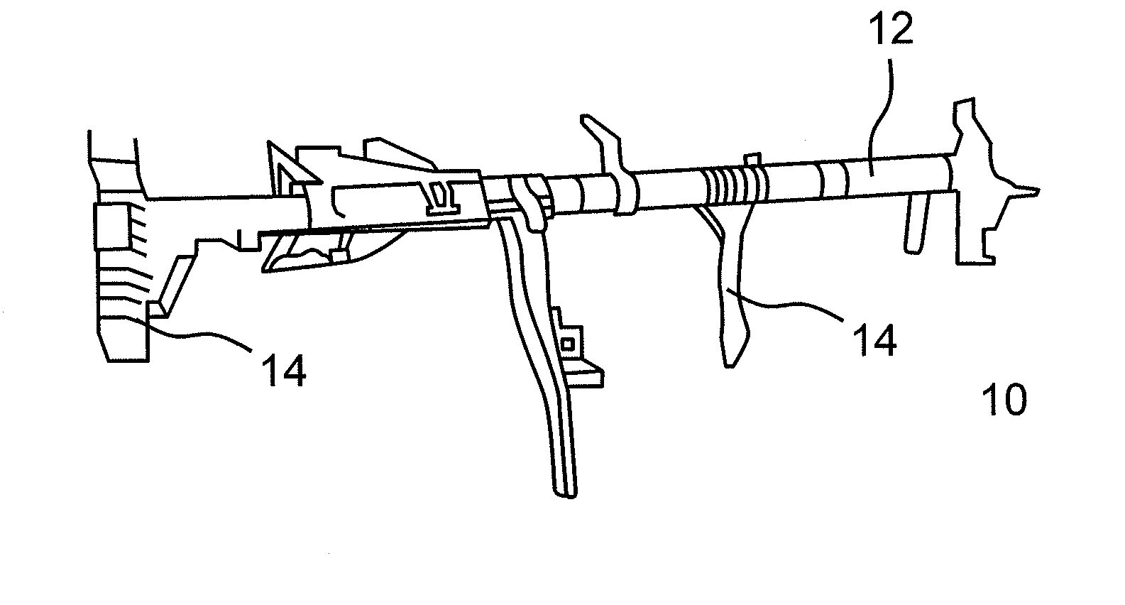
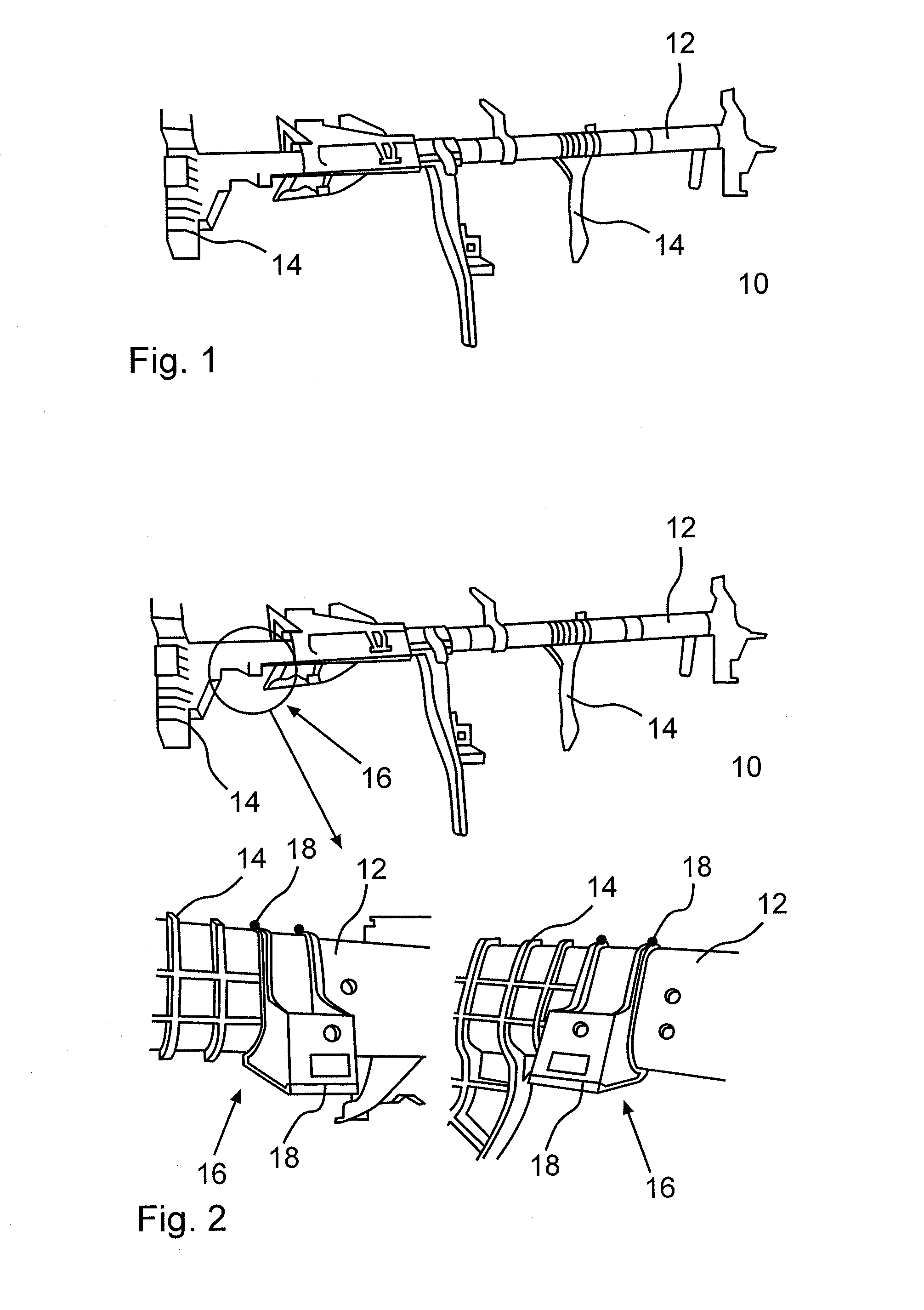
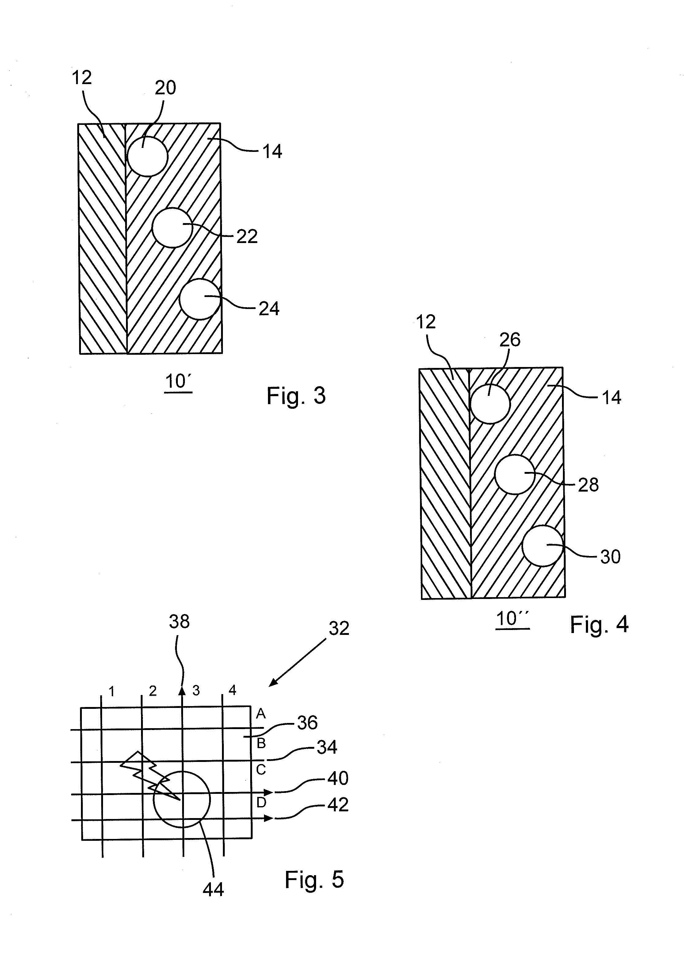
[0040]While FIGS. 1 and 2 illustrate a possible embodiment of an arrangement of an electric conductor on a plastic / metal cross-member for detecting a deformation or damage of the cross-member, FIGS. 3 to 5 illustrate possibilities of applying such electric and / or optical conductors for detecting the deformation or damage of the plastic material of the cross-member or of arranging them in a matrix for locating the deformation or damage.

[0041]Identical elements are identified by the same reference numbers in the figures.

[0042]FIG. 1 shows a plastic / metal hybrid component in the form of a cross-member 10 for a motor vehicle, which hybrid component comprises a base component 12 made of a metallic material, parts of which have been supplemented by a plastic material 14 to provide the said plastic / metal hybrid component. The cross-member 10 reinforces the passenger car and accommodates components located in its region.

[0043]As a deformation or a damage of the cross-member 10 can occasiona...


PUM


Abstract

A hybrid component supporting component for a motor vehicle includes a base component made of a metallic material, at least some parts of which are provided with a plastic material. The hybrid component includes a detection device having at least one conductor element by means of which a deformation of the hybrid component can be detected.

Description

BACKGROUND AND SUMMARY OF THE INVENTION[0001]The invention relates to a hybrid component a method for manufacturing such a hybrid component.[0002]Generic components for a car body are sufficiently well known. They are designed as plastic / metal hybrid components or made from a fiber-reinforced plastic material and perform important supporting functions in the passenger car. While the car travels, such a component is subjected to continuously varying loads which result in the elastic deformation of the component. Excessive loading, for example in an accident or as a result of advanced ageing at the end of the service life of the component, may lead to a permanent deformation of the component or affect the function of the component.[0003]Such damage cannot be detected easily when examining the car. Moreover, hybrid components used as structural components of the car body are often only accessible, if at all, after the removal of whole system, which results in high service or repair cos...

Claims


Application Information

Patent Timeline
IPC IPC(8): G01B7/16
CPCB60R21/0136B62D25/145B62D29/004B62D41/00B62D21/17B62D29/001
Inventor KROPLA, OLIVER
Owner DAIMLER AG
Why Eureka
Try Eureka