High frequency power amplifier

a power amplifier and high frequency technology, applied in the direction of amplifiers with tubes, waveguide devices, phase splitters, etc., can solve the problems of amplifiers becoming bigger, amplifiers becoming smaller, and the distortion characteristic of amplifiers was bad, so as to improve the cancelling effect

Inactive Publication Date: 2012-07-26
NEC CORP
View PDF1 Cites 4 Cited by
  • Summary
  • Abstract
  • Description
  • Claims
  • Application Information

AI Technical Summary

Benefits of technology

[0018]The left-handed transmission line and a right-handed transmission line are combined to provide an output side balun circuit and a phase difference in the fundamental wave is generated between the left-handed transmission line and the right-handed transmission line. In addition, it is possible to improve a cancelling effect for the second harmonic and the third harmonic by controlling values of each inductor and each condenser.

Problems solved by technology

However, due to a frequency dependence of the difference of balun circuit length, a perfect cancelling effect can not obtained.
That is, it was difficult with the above mentioned balun circuit of the related art to realize a difference of ½ wave length for the fundamental wave, a difference of ½ wave length for the second harmonic and no difference of wave length for the third harmonic at same time.
For this reason, the distortion characteristic of the amplifier was bad, and, to obtain a desired distortion characteristic of a system, there were a need to add a supplementary distortion compensation circuit and a problem that the amplifier becomes bigger.

Method used


Image

  • High frequency power amplifier
  • High frequency power amplifier
  • High frequency power amplifier

Examples


Embodiment Construction

[0028]Hereinafter, an exemplary embodiment to realize a power amplifier of the present invention and its power amplifying method is described with reference to attached drawings.

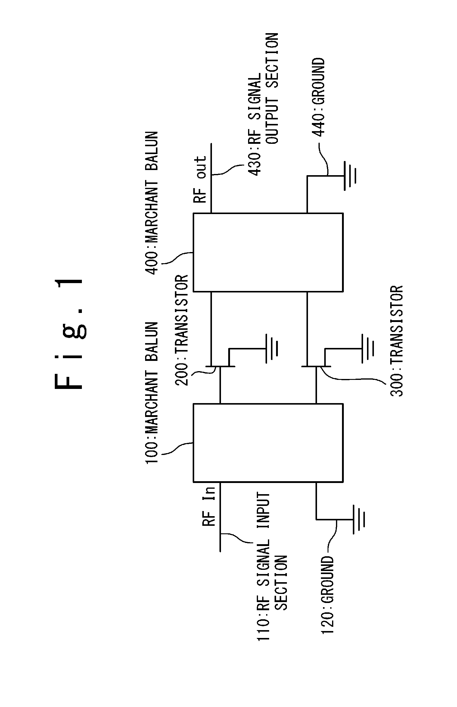
[0029]FIG. 3 is a block diagram for explaining an overall configuration of the power amplifier of an exemplary embodiment of the present invention. This power amplifier includes a marchant balun 100, a first transistor 200, a second transistor 300 and an output side balun circuit 400. However, in FIG. 3, a bias circuit for the two transistors 200 and 300 to work is not shown.

[0030]The marchant balun 100 includes an RF signal input section 110, aground end grounded to a ground 120, a first output section and a second output section.

[0031]The first transistor 200 and the second transistor 300 have a same characteristic and perform a push-pull type power amplification. Here, an FET is used as an example of a transistor, but other transistors can be used instead. The explanation is continued by assuming that eac...


PUM


Abstract

A power amplifier includes an amplifying circuit, and first through third transmission lines. The amplifying circuit amplifies an input signal having a fundamental frequency to generate a first amplified signal and a second amplified signal whose phase is opposed to the first amplified signal. The first transmission line adds a first group of phases, different in correspondence with a frequency, to the first amplified signal by using a left-handed material to generate a first transmission signal. The second transmission line adds a second group of phases, different in correspondence with a frequency, to the second amplified signal by using a right-handed material to generate a second transmission signal. The third transmission line overlaps the first and the second transmission signals to generate an output signal. The first and the second group of phases include a phase difference configured to weaken a second harmonic and a third harmonic.

Description

TECHNICAL FIELD[0001]This invention is related to a power amplifier and its power amplifying method, and especially, is related to a push-pull type power amplifier and its amplifying method.BACKGROUND ART[0002]As it is represented by mobile base stations, signal modulation is becoming more sophisticated in a purpose of improving a transmission rate. As a result, an amplifier is required with a high distortion characteristic, and a need is arising to make the amplifier work with a back-off bigger than a saturated output state. Therefore, a higher output is required to the amplifier. As a solution, a method of overlapping electric powers, such as a push-pull type amplifier, is used.[0003]FIG. 1 is a block diagram showing a configuration of a push-pull type high frequency power amplifier by a related art. In FIG. 1, the power amplifier of the related art includes a first marchant balun 100 as an input side balun circuit, a first transistor 200, a second transistor 300 and a second marc...

Claims


Application Information

Patent Timeline
Patent Type & Authority Applications(United States)
IPC IPC(8): H03F3/26
CPCH01P5/10H03F1/3205H03F2200/09H03F2200/06H03F3/604
Inventor WAKEJIMA, AKIO
Owner NEC CORP
Why Eureka
Try Eureka