
Silencing arrangement

a technology of arrangement and silence, applied in the direction of motors, applications, sound producing devices, etc., can solve the problems of intense fan tone, annoying user of appliances, and fan generated by rotating fans, and achieve the effect of enhancing the sound cancelling effect of such an arrangement and simplifying both manufacture and assembly

Inactive Publication Date: 2011-04-12
DYSON TECH LTD
View PDF13 Cites 23 Cited by
  • Summary
  • Abstract
  • Description
  • Claims
  • Application Information

AI Technical Summary

Benefits of technology

The provision of first and second sets of silencers provides a greater noise cancelling effect at the tone or tones of interest than one set alone. In spacing the silencers in two directions, the overall effect is that of an array of closely interposed silencers acting on sound waves generated by different regions of the fan.
One set of silencers may be formed as an integral part of a housing for the motor and fan unit. This arrangement simplifies both manufacture and assembly, and ensures that the tube silencers of that set are in predetermined positions with respect to the fan.
One or both sets of silencers may be tuned to a frequency of interest, such as the BPF of the fan in a mode of operation. The sound cancelling effect of such an arrangement is enhanced by axially spacing the first and second sets by an integral number of half-wavelengths corresponding to the frequency of interest.

Problems solved by technology

A problem which may be encountered with such appliances is that of tones generated by the rotating fan.
Such a fan tone can be intense and annoying for a user of the appliance.

Method used


Image

  • Silencing arrangement
  • Silencing arrangement
  • Silencing arrangement

Examples


Embodiment Construction

Like reference numerals refer to like parts throughout the specification.

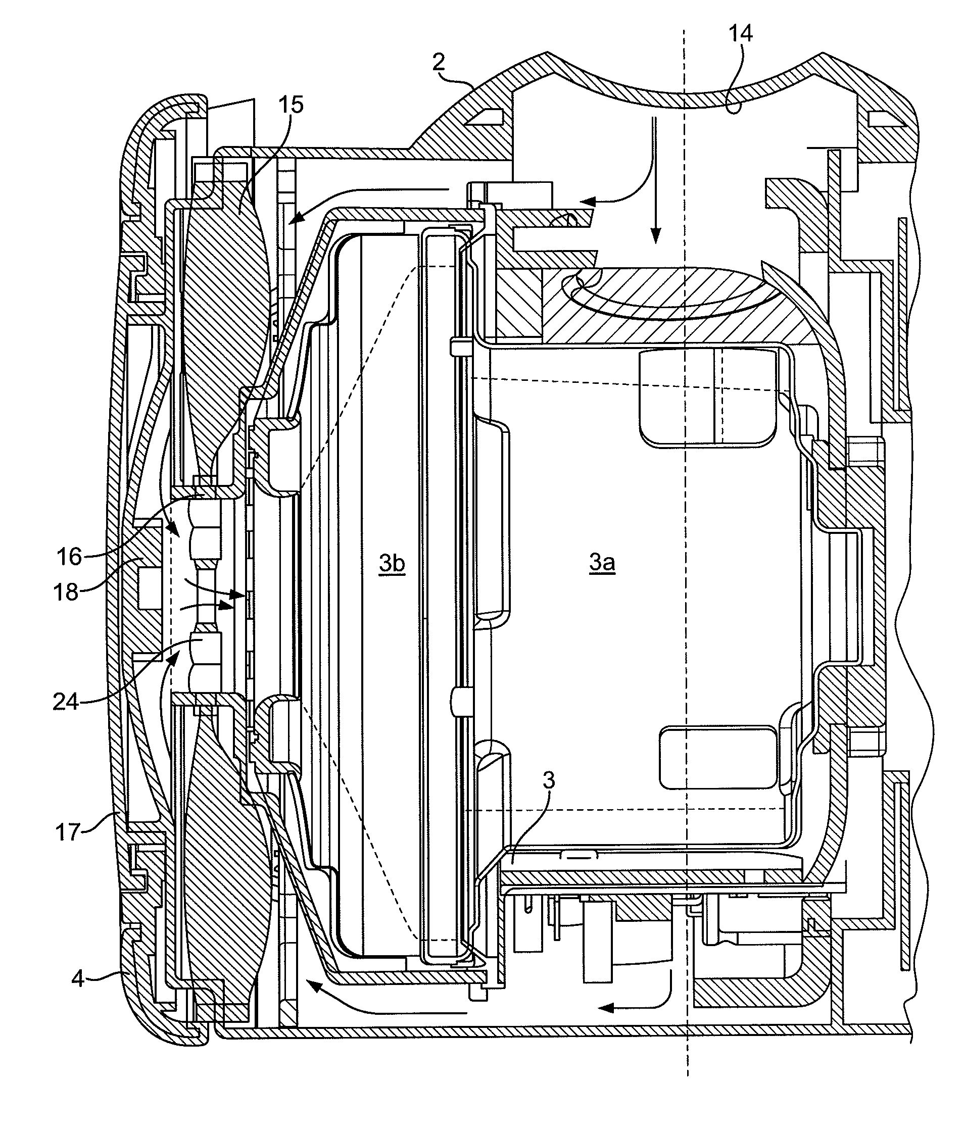
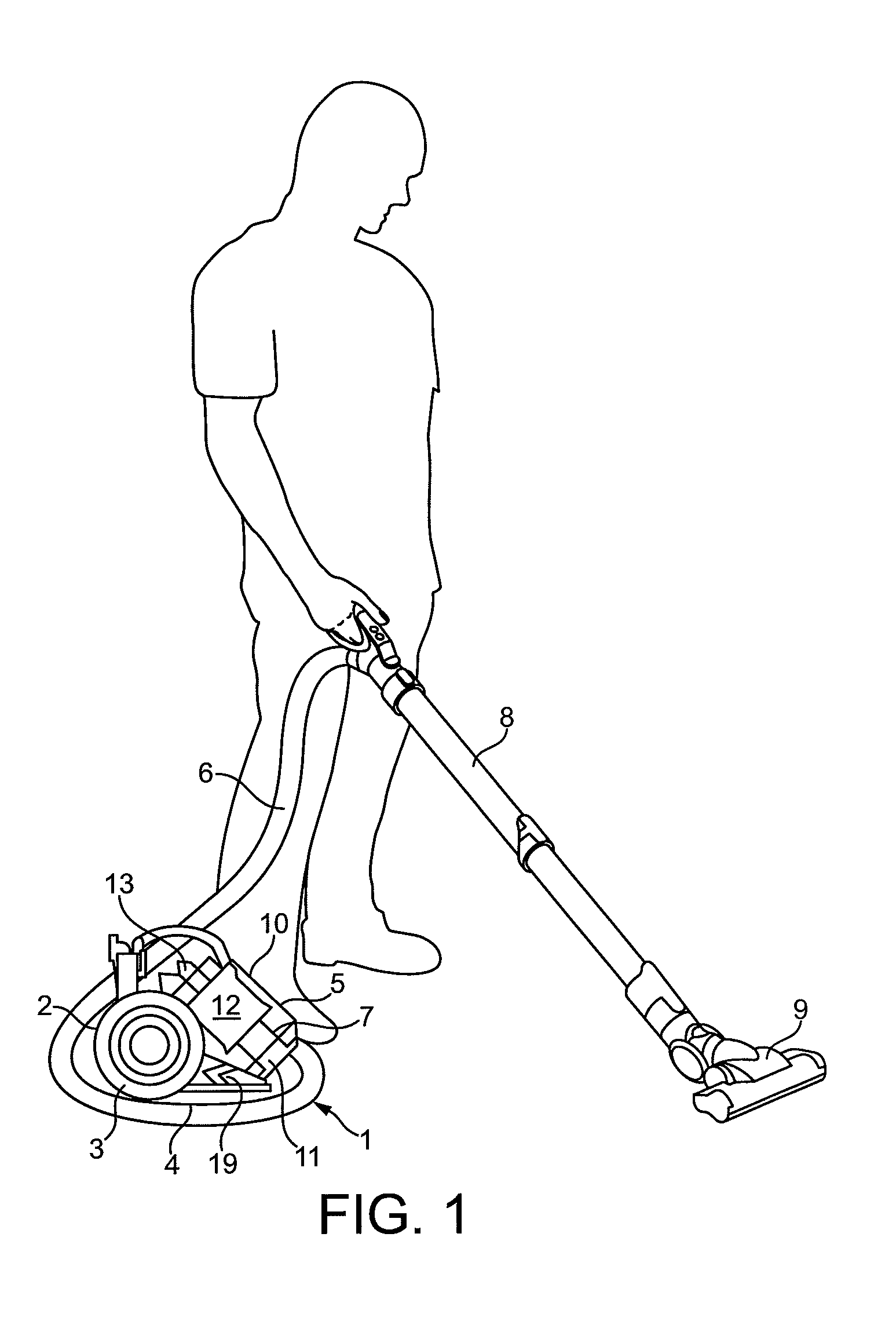
With reference to FIG. 1, a surface-treating appliance is shown in the form of a cyclonic vacuum cleaner 1. The vacuum cleaner 1 has a main body 2 housing a motor and fan unit 3. The main body 2 includes means for allowing it travel across a floor surface, which, in this embodiment, comprises a pair of wheels 4. Separating apparatus in the form of a cyclonic separator 5 is releasably attached to the main body 2. A flexible hose 6 is connectable to an inlet port 7 on the main body 2. The other end of the flexible hose 6 is connectable to a wand 8, the distal end of which is adapted to receive a floor tool 9. During use, the main body 2 of the vacuum cleaner 1 is pulled along the floor surface by the flexible hose 6 as a user moves around a room. When the user switches on the vacuum cleaner 1, the motor 3a (FIG. 2) is energized and drives a fan 3b so as to draw in dirty air through the floor tool 9. The dirty air...


PUM


Abstract

In an appliance, such as a cyclonic vacuum cleaner, a motor is arranged to drive an impeller fan located in a motor and fan unit. The rotation of the impeller may cause nuisance tones to be generated. A silencing arrangement is provided to control such noise and includes a plurality of discrete passive silencers in the form of tube silencers arranged in a first set and a second set. The tube silencers have open end portions arranged to face the fan and the silencers of the first set are spaced from the silencers of the second set in both axial and radial directions. This combination gives the same effect as an array of closely spaced tube silencers—however, by spacing the silencers in two directions, fluid is allowed to flow freely.

Description

REFERENCE TO RELATED APPLICATIONSThis application claims the priority of United Kingdom Application No. 0903411.7, filed 27 Feb. 2009, the entire contents of which are incorporated herein by reference.FIELD OF THE INVENTIONThe present invention relates to a silencing arrangement arranged to control fan tone noise of a motor and fan unit, such as is employed in a vacuum cleaner.BACKGROUND OF THE INVENTIONIn a typical vacuum cleaner, Vacuum cleaners are designed to separate dirt and dust from an airflow. In a typical vacuum cleaner, the motor and fan unit generates an airflow which draws dirt- and dust-laden air into the vacuum cleaner through a dirty air inlet. The airflow then passes through a form of separating apparatus to remove dirt and dust from the airflow. Some vacuum cleaners make use of a porous bag through which the dirty air is sucked so that the dirt and dust is retained in the bag whilst cleaned air is exhausted to the atmosphere. In other vacuum cleaners, cyclonic sepa...

Claims


Application Information

Patent Timeline
Patent Type & Authority Patents(United States)
IPC IPC(8): F01N13/00
CPCA47L9/0081F01N1/00F04D29/66G10K11/16A47L9/00A47L9/28
Inventor LIDDELL, SARAH HELEN
Owner DYSON TECH LTD
Learn More