
Non-invasive Thermal Dispersion Flow Meter with Chronometric Monitor for Fluid Leak Detection

a flow meter and non-invasive technology, applied in the field of fluid leakage detection, can solve the problems of extreme structural damage, water loss for the entire structure, and property uninsurable,

Active Publication Date: 2012-07-19
SENTINEL HYDROSOLUTIONS
View PDF53 Cites 70 Cited by
  • Summary
  • Abstract
  • Description
  • Claims
  • Application Information

AI Technical Summary

Benefits of technology

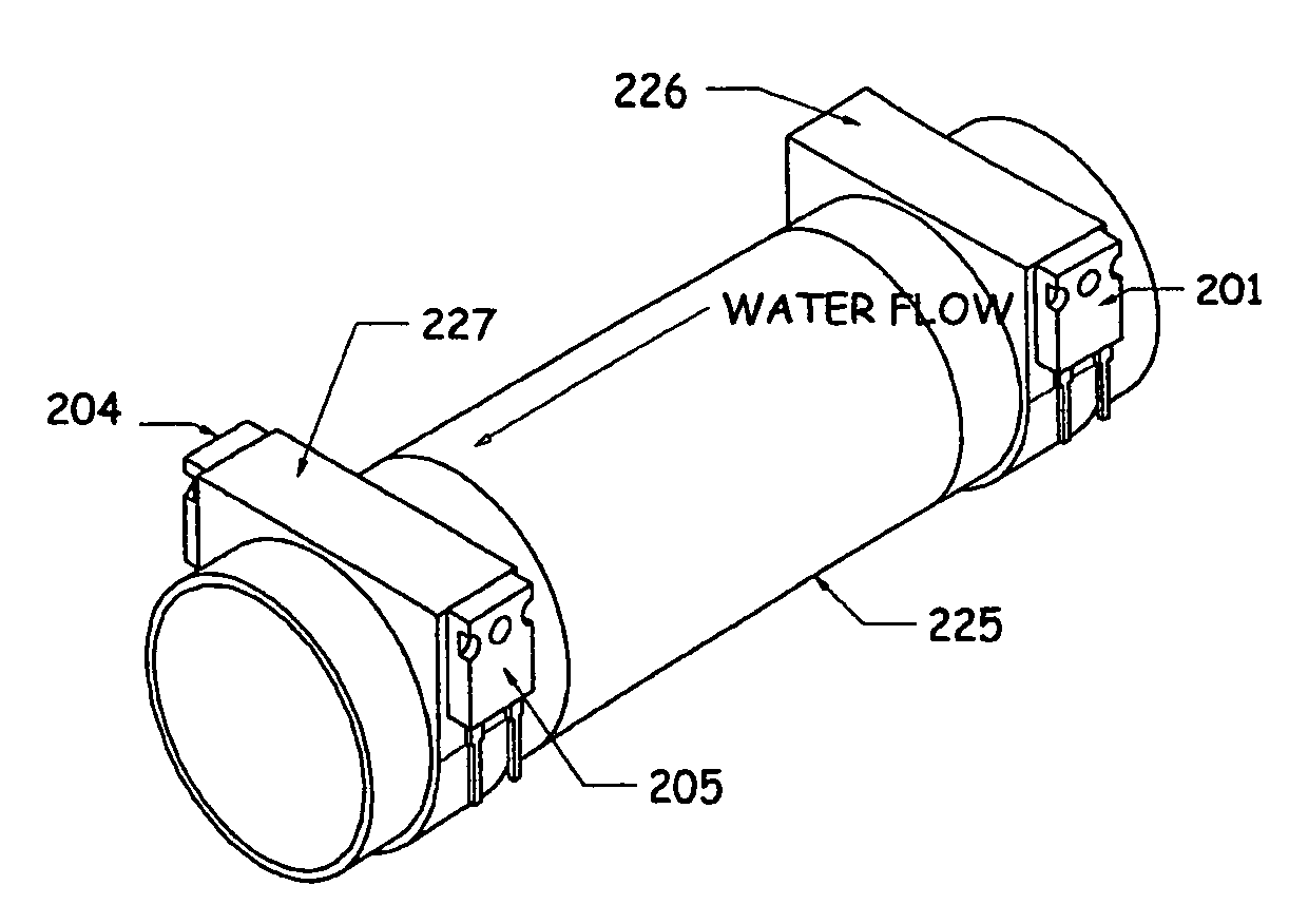
The present invention is a water leak detection system for residential and commercial buildings. The system uses sensors that can detect water leaks from pressurized pipes or fixtures. The sensors have no moving parts, are durable, and can detect small amounts of water flow. The system can trigger an alarm if water flows continuously for a set time without stopping. The alarm can alert the homeowner or a surveillance company monitoring the premises. The system includes user guides and features to aid in detecting leaks. The system measures the temperature at the upstream and downstream clamps in a pipe, and the flow rate of fluid in the pipe is proportional to the heat energy added by the heating element. The control panel is easy to use and can activate a shut-off valve to shut off water to the structure. The system can also be connected to an auto-dialer telephone device or an electric water valve for automatic shut-off. The technical effects of the invention are that it can detect leaks quickly, prevent damage to structures, and save money on water usage and insurance claims.

Problems solved by technology

An undetected slab leak (a broken pipe in or under a concrete slab floor) can cause extreme structural damage in excess of thousands of dollars, and render the property uninsurable from the resulting insurance claim.
Not just water loss under the hot water heater or dishwasher or an icemaker like other point of leak detection competitive devices, but water loss for the entire structure.

Method used


Image

  • Non-invasive Thermal Dispersion Flow Meter with Chronometric Monitor for Fluid Leak Detection
  • Non-invasive Thermal Dispersion Flow Meter with Chronometric Monitor for Fluid Leak Detection
  • Non-invasive Thermal Dispersion Flow Meter with Chronometric Monitor for Fluid Leak Detection

Examples


Embodiment Construction

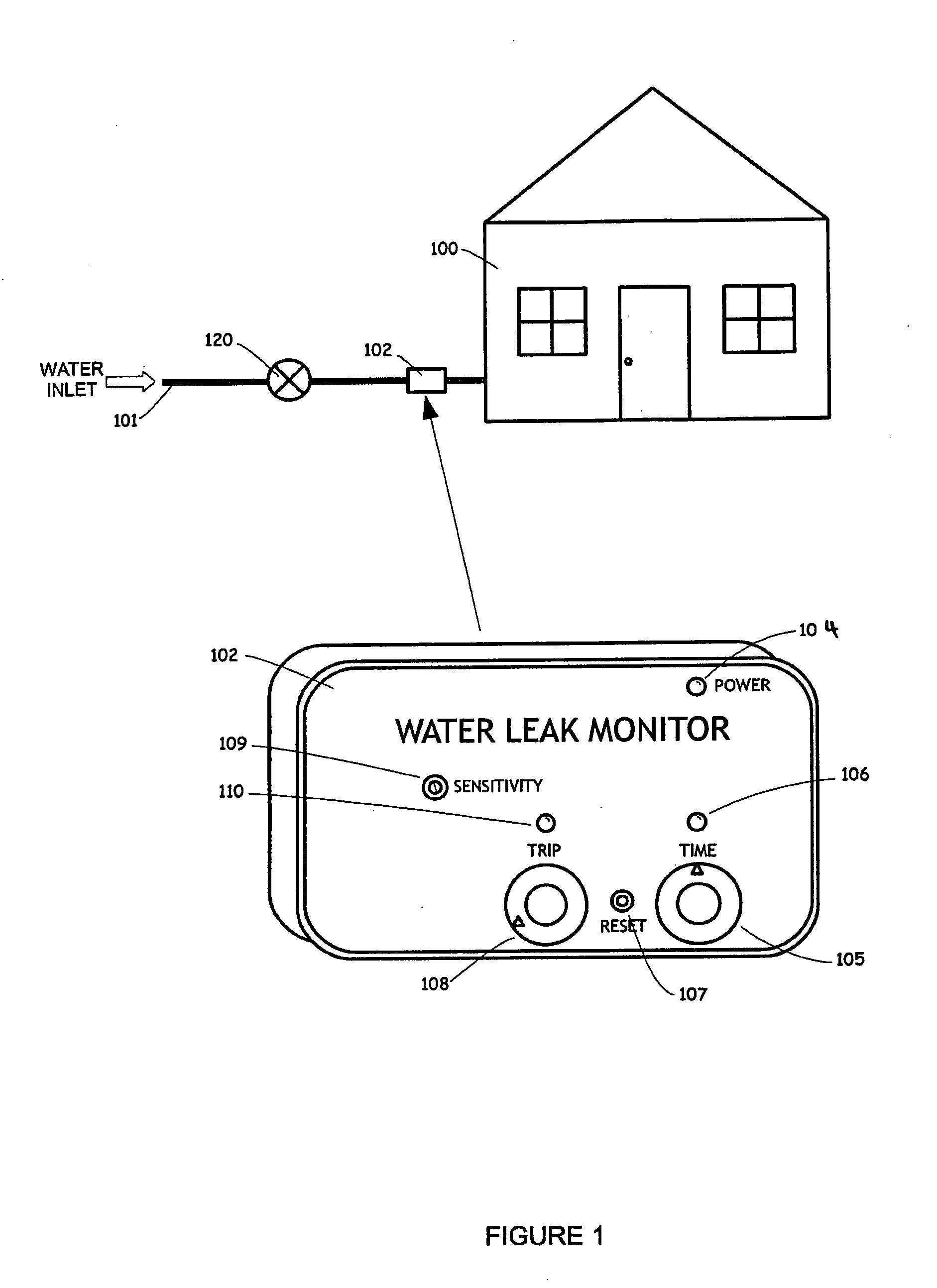
[0031]This invention relates to an electronic thermal monitor system intended to measure fluid flow within a conduit or pipe, by clamping directly to the outside of a pipe or onto a thermally conductive heat transfer medium between the fluid and the system. Referring to FIG. 1, the present invention is suitable for application of leak detection technology into a structure 100 having a water inlet 101, a water leak monitor 102, and a shut off valve 120. The water leak monitor 102 includes a power indicator 104, a timer set 105 with an indicator 106, and a trip level set 108 with an indicator 110. Sensitivity adjustment 109 provides a user the ability to adjust the sensitivity of the device. A reset button 107 is provided to allow for the system to be reset after an alarm condition has been generated.

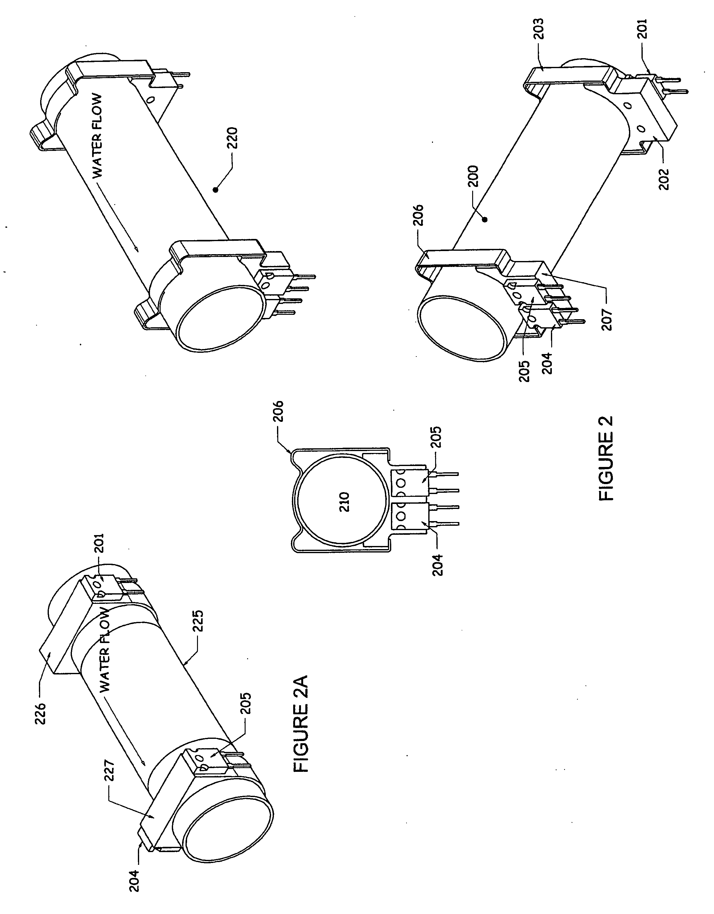
[0032]In an exemplary embodiment, this invention is discussed in conjunction with a typical thin wall copper pipe section commonly found in commercial and residential plumbing systems tha...


PUM


Abstract

A non-invasive thermal dispersion flow meter with chronometric monitor for fluid leak detection includes a heater, an ambient temperature sensor and a flow rate sensor which are configured to sense the temperature of a fluid in a conduit, and then monitor the flow of that fluid through the conduit. The fluid flow sensor is incorporated into a Wheatstone bridge circuit which is used to provide increased sensitivity to the outputs of the sensors. Based upon the ambient temperature sensor readings, the flow rate sensor and heater may be adjusted to optimize the operation of the system to detect leaks. An alternative embodiment utilizes a single sensor and separate heater which work together to determine heat propagation times which in turn is used to calculate flow rate.

Description

RELATED APPLICATIONS[0001]The application is a patent application and claims priority to U.S. Provisional Patent Application Ser. No. 61 / 429,242 filed Jan. 3, 2011 entitled “Noninvasive Thermal Dispersion Flow Meter with Chronometric Monitor for Fluid Leak Detection”, and currently co-pending, and to U.S. Provisional Patent Application Ser. No. 61 / 542,793 filed on Oct. 3, 2011 entitled “Direct Pipe Clamp on Flow Meter Leak Detector”, and currently co-pending.FIELD OF INVENTION[0002]The present invention relates generally to the field of fluid leakage detection. More particularly, the present invention relates to devices useful for the monitoring and evaluation of fluid flow rates. The present invention is more particularly, through not exclusively, useful as a non-invasive leak detection system capable of detecting even the smallest fluid leakage within a fluid conduit system, terminating fluid flow in response to the leak, and providing other indication, alert, and control function...

Claims


Application Information

Patent Timeline
Patent Type & Authority Applications(United States)
IPC IPC(8): F16K31/12G01M3/00
CPCG01M3/2807G01M3/002Y10T137/7761G01K13/026E03B7/003E03B7/072G01K7/22G01K13/02
Inventor PALLAIS, SCOTT
Owner SENTINEL HYDROSOLUTIONS
Learn More