
Non-invasive thermal dispersion flow meter with fluid leak detection and alert

a flow meter and thermal dispersion technology, applied in the direction of instruments, fluid-tightness measurement, and measurement of fluid loss/gain rate, can solve the problems of extreme structural damage, property uninsurable, and water loss for the entire structur

Active Publication Date: 2017-01-03
SENTINEL HYDROSOLUTIONS
View PDF36 Cites 2 Cited by
  • Summary
  • Abstract
  • Description
  • Claims
  • Application Information

AI Technical Summary

Benefits of technology

[0013]In the preferred embodiment, two separate sensor probes are clamped directly onto the outside of a pipe or thermally conductive heat transfer medium between the fluid and the system to allow detection of all flow conditions. Not just water loss under the hot water heater or dishwasher or an icemaker like other point of leak detection competitive devices, but water loss for the entire structure. A comprehensive system may include moisture sensors together with the leak detection system. This will ensure both immediate and long-term protection of the structure and its contents and detect leaks from the pressurized supply side as well as the drain and waste systems, appliances, and water intrusion from the outside environment. Resource conservation and water cost savings are also promoted by detecting unknown water loss long before thousands of gallons escape down the drain or into the structure's foundation.
[0015]In an alternative embodiment, a single temperature sensor and a separate heating element are clamped onto a pipe. The heating element is located a few inches downstream from the temperature sensor. The sensor and the heating element are both wrapped with insulation thereby isolating the sensor and heating element from ambient conditions and increasing the accuracy of the measurements and the sensitivity of the system. This embodiment works by measuring temperature before the heater is energized, then energizing the heater for a predetermined period of time. The temperature is continuously monitored to determine the amount of time for the heat energy added by the heater to propagate to the temperature sensor. That amount of time is used to determine the flow rate in the pipe. The longer the time for the heat energy to reach the sensor, the higher the flow rate is within the pipe. The shorter the time for the heat energy to reach the sensor, the lower the flow rate is within the pipe. After the propagation time is determined, the heater is deenergized to allow it and the sensor to return to ambient conditions so a new test can be performed.
[0016]In an alternative embodiment, the addition of an external environment sensor probe and temperature sensor package to a leak detection system creates a more comprehensive system able to prevent and detect leaks. The alternative embodiment works by taking the temperature at the temperature sensor package of the leak detection system, the external environment temperature sensor, and the additional temperature sensor package and feeding the data to a microprocessor where they are analyzed to determine whether the fluid is expanding by comparing the temperature data to the user inputted data stored in a control ROM and flash memory. If expansion is occurring, the microprocessor will open a relief valve and cause fluid to flow, releasing excess pressure and preventing damage to the structure's pipe system. In extreme conditions, the microprocessor will shut off the isolation valve to prevent additional fluid from entering the system and open a relief valve and cause fluid to flow, releasing excess pressure in the system. The microprocessor will then open an air valve to aid the evacuation of the fluid in the system.
[0017]The control panel is easy to use and attractive. Its display provides real-time system and flow status. The Panel will indicate an alarm condition; the flow level when the alarm occurred, and sound a built-in beeper, then if no action is taken it will activate an industrial quality motor-driven ball valve to shut off the water to the structure. The control panel will then display information to guide the homeowner through the process of detecting simple leaks such as a dripping faucet. The panel can also be used to select other operating modes or select other features of the leak detection system such as monitoring the fluid temperature and external environment temperature to prevent overpressure of the structure's pipe system

Problems solved by technology

An undetected slab leak (a broken pipe in or under a concrete slab floor) can cause extreme structural damage in excess of thousands of dollars, and render the property uninsurable from the resulting insurance claim.
Not just water loss under the hot water heater or dishwasher or an icemaker like other point of leak detection competitive devices, but water loss for the entire structure.

Method used


Image

  • Non-invasive thermal dispersion flow meter with fluid leak detection and alert
  • Non-invasive thermal dispersion flow meter with fluid leak detection and alert
  • Non-invasive thermal dispersion flow meter with fluid leak detection and alert

Examples


Embodiment Construction

[0034]This invention relates to an electronic thermal monitor system intended to measure fluid flow within a conduit or pipe, by clamping directly to the outside of a pipe or onto a thermally conductive heat transfer medium between the fluid and the system.

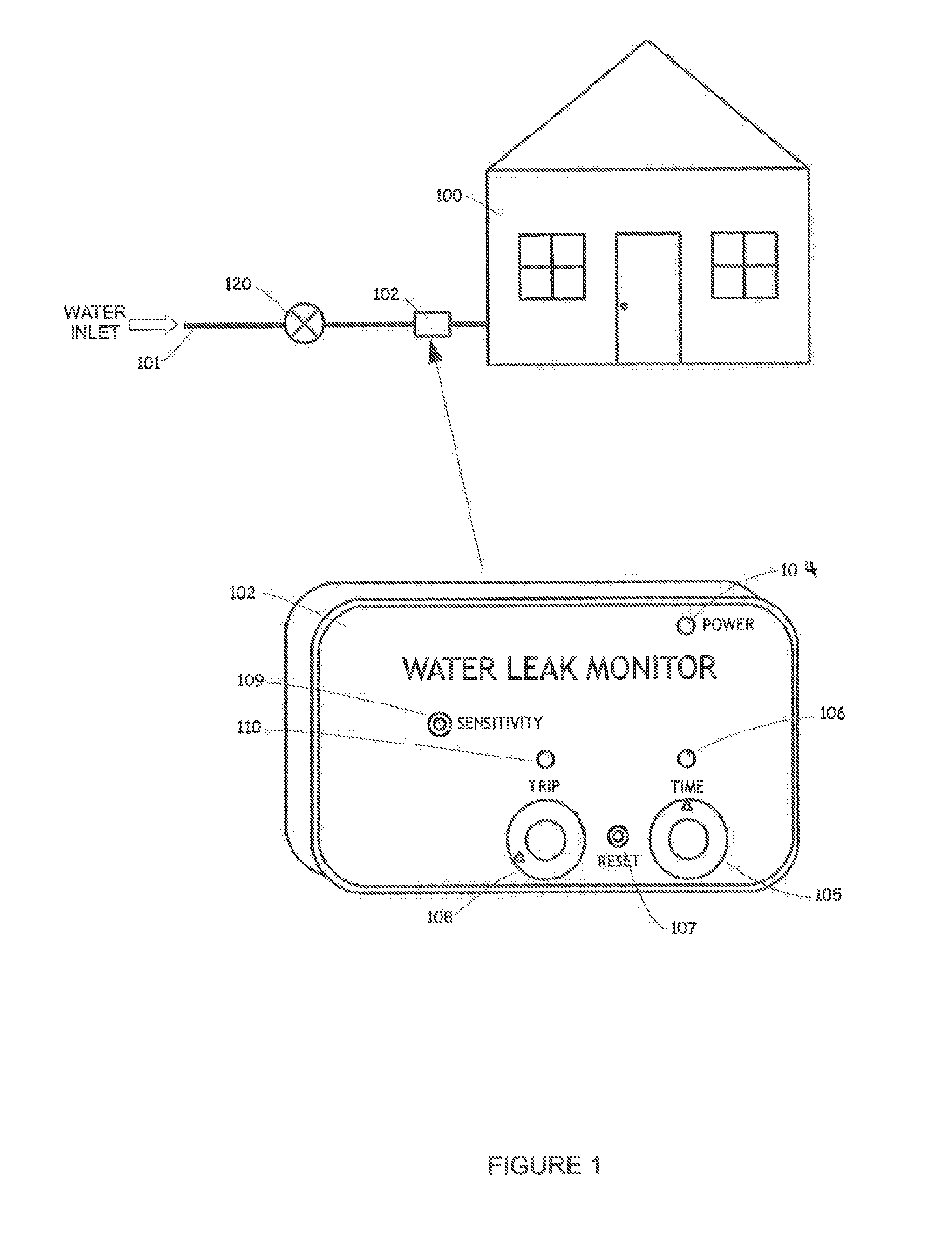
[0035]Referring to FIG. 1, the present invention is suitable for application of leak detection technology into a structure 100 having a water inlet 101, a water leak monitor 102, and a shut off valve 120. The water leak monitor 102 includes a power indicator 104, a timer set 105 with an indicator 106, and a trip level set 108 with an indicator 110. Sensitivity adjustment 109 provides a user the ability to adjust the sensitivity of the device. A reset button 107 is provided to allow for the system to be reset after an alarm condition has been generated.

[0036]In an exemplary embodiment, this invention is discussed in conjunction with a typical thin wall copper pipe section commonly found in commercial and residential plumbing system...


PUM


Abstract

A non-invasive thermal dispersion flow meter with chronometric monitor for fluid leak detection includes a heater, an ambient temperature sensor and a flow rate sensor which are configured to sense the temperature of a fluid in a conduit, and then monitor the flow of that fluid through the conduit. The fluid flow sensor is incorporated into a Wheatstone bridge circuit which is used to provide increased sensitivity to the outputs of the sensors. Based upon the ambient temperature sensor readings, the flow rate sensor and heater may be adjusted to optimize the operation of the system to detect leaks. An alternative embodiment utilizes a single sensor and separate heater which work together to determine heat propagation times which in turn is used to calculate flow rate. Based on the sensor readings, the flow may be adjusted to prevent damage and leaks by relieving the system of excess pressure.

Description

RELATED APPLICATIONS[0001]This application is a Divisional and claims the benefit of priority to continuation-in-part U.S. Utility patent application Ser. No. 13 / 899,450 filed May 21, 2013 entitled “Non-invasive Thermal Dispersion Flow Meter with Chronometric Monitor for Fluid Leak Detection and Freeze Burst Prevention”, and currently co-pending, which in turn claims benefit of priority to U.S. Utility patent application Ser. No. 13 / 342,961 filed Jan. 3, 2012 entitled “Noninvasive Thermal Dispersion Flow Meter with Chronometric Monitor for Fluid Leak Detection,” and currently co-pending, which in turn claims benefit of priority to U.S. Provisional Patent Application Ser. No. 61 / 429,242 filed Jan. 3, 2011 entitled “Noninvasive Thermal Dispersion Flow Meter with Chronometric Monitor for Fluid Leak Detection”, and currently co-pending, and to U.S. Provisional Patent Application Ser. No. 61 / 542,793 filed on Oct. 3, 2011 entitled “Direct Pipe Clamp on Flow Meter Leak Detector”, and curre...

Claims


Application Information

Patent Timeline
Patent Type & Authority Patents(United States)
IPC IPC(8): G01M3/28G01M3/00E03B7/00
CPCG01M3/2807E03B7/003G01M3/002
Inventor TRESCOTT, ROBERTSHAW, SCOTT
Owner SENTINEL HYDROSOLUTIONS
Learn More