
Device and method to prevent improper fluid mixing ratios in two component materials

a technology of fluid mixing and two components, applied in water supply installations, process and machine control, instruments, etc., can solve the problems of inability to achieve large-volume production, prohibitively expensive devices for smaller production operations, and prior-art mixing devices that do not provide a reliable, effective, cost-effective means

Inactive Publication Date: 2012-07-19
MELLETTE ROBERT RAY
View PDF8 Cites 3 Cited by
  • Summary
  • Abstract
  • Description
  • Claims
  • Application Information

AI Technical Summary

Benefits of technology

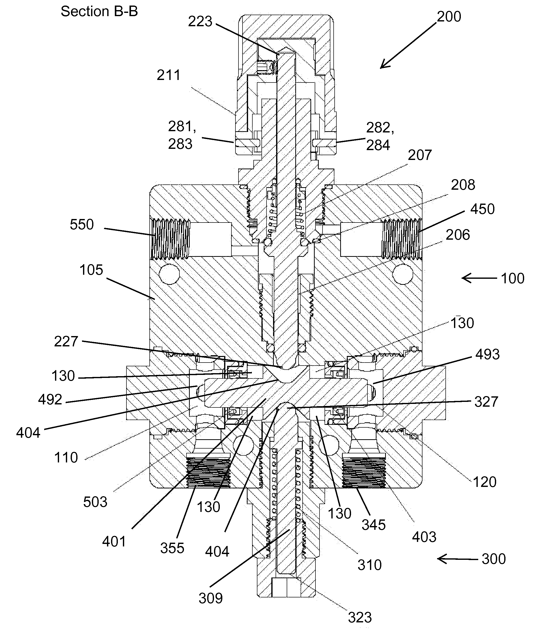
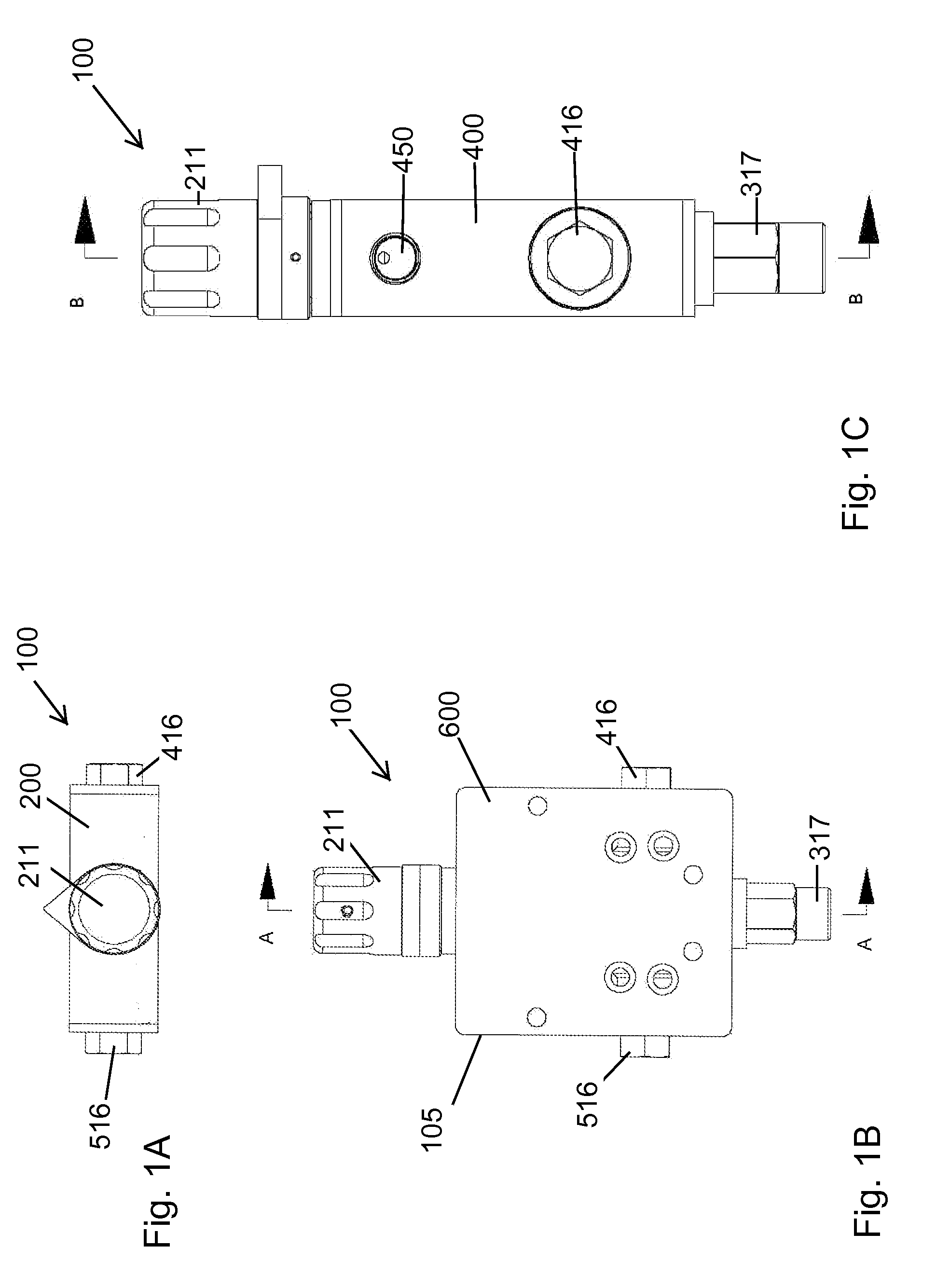
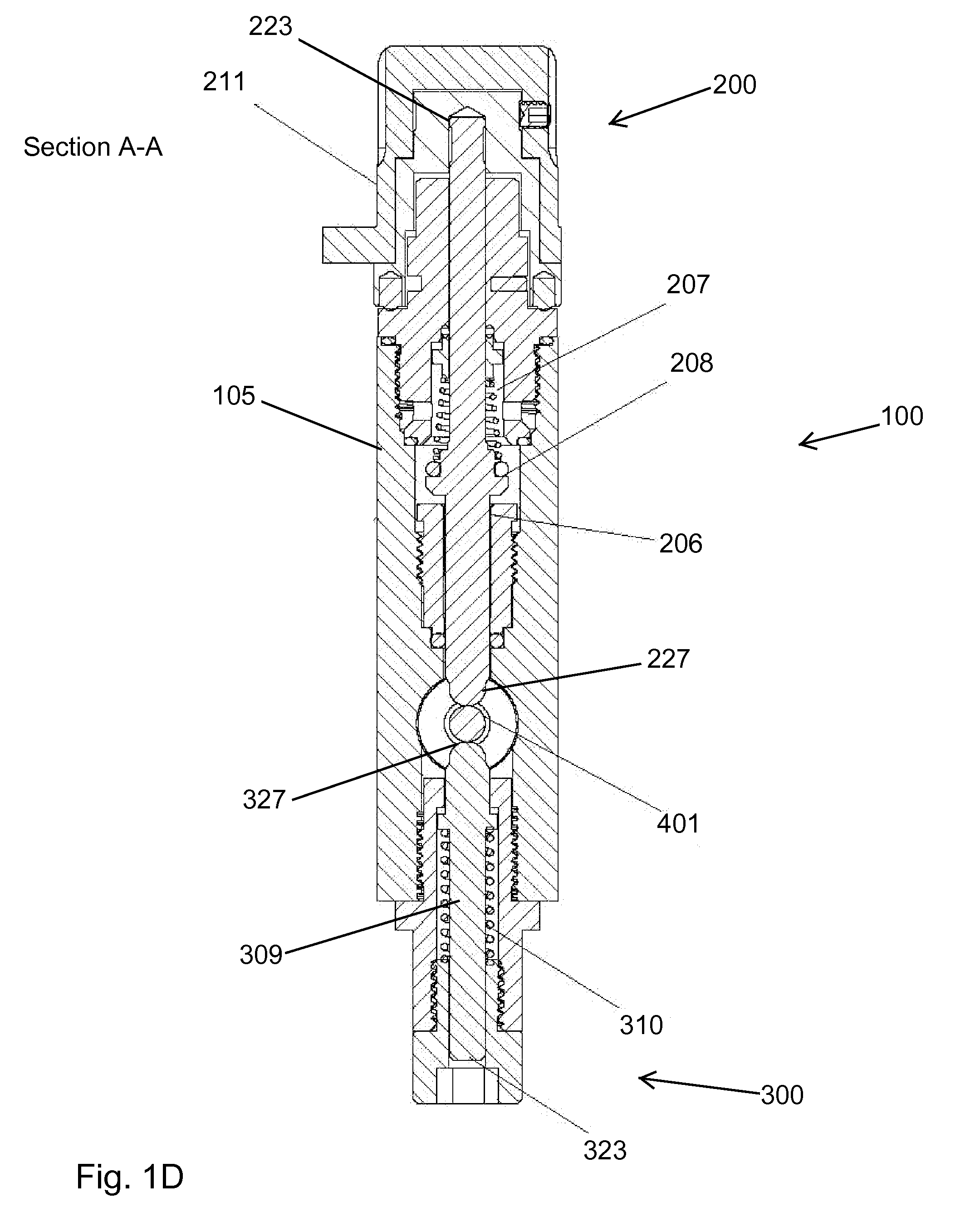
[0014]Certain embodiments of the present disclosure relate to an apparatus and method for maintaining a fluid mixing ratio. The apparatus according to various embodiments prevents a fluid flow imbalance between two proportionate fluid streams based on a pressure difference, and may be configured to alert the user and / or stop the fluid flow in the event of a fluid flow imbalance. The apparatus is formed such that two plunger components engage a shuttle piston, the shuttle piston configured to move one or more plunger components given a selectable fluid flow imbalance. Other embodiments and alternatives to this device are described in greater detail below.
[0023]The second plunger, diametrically opposed to the first plunger along the shuttle piston, creates additional centering force to the shuttle piston thereby further resisting axial (that is, longitudinal) movement of the shuttle piston, in turn increasing the threshold value of pressure differential between device left-side chamber and device right-side chamber below which the shuttle piston will not move. This threshold value is established by the combined spring force applied to the first plunger and the second plunger and the diameter of the shuttle piston.
[0024]Generally, the device is in fluid communication with a first fluid through device bottom right side pressure port and a second fluid through device left side pressure port. The first fluid maintains a nominal pressure one or first pressure, and the second fluid maintains a nominal pressure two or second pressure. The nominal pressure maintained in device right side chamber, which is in fluid communication with first fluid, is the same as that of first fluid. Similarly, the nominal pressure maintained in device left side chamber, which is in fluid communication with the second fluid, is the same as that of second fluid. When in steady-state and / or nominal operation, the first fluid and the second fluid are at substantially the same pressure, and thus each of the device right side chamber and the device left side chamber are at the same pressure and exert a substantially equal and opposite force against the shuttle piston right side and the shuttle piston left side, respectively, and the shuttle piston maintains a centered or nominal position substantially centered about the device vertical centerline and each of the first plunger and second plunger maintain a nominal position. However, when a predetermined and selectable pressure differential between the first fluid and the second fluid exists (and thus a pressure differential exists between the device right side chamber and the device left side chamber), the shuttle piston will traverse along its axial axis, which in turn will move the respective proximal ends of each of first plunger and second plunger vertically and away from the center area of the device as described above. The vertical movement of the first plunger and second plunger provide a means to alert the user and / or stop the fluid flow of the fluid flow imbalance event.
[0026]In another embodiment, the device may be configured in a locked-out configuration state. This locked-out state is particularly useful to prevent unwanted actuation of the poppet air shut-off valve and subsequent stoppage of external equipment during operational modes. The locked-out state would be useful during, for example, pump priming or system flushing or any situation that requires or causes unbalanced pressure between the two to-be-mixed fluids (such as a base and catalyst). In one embodiment of the locked-out configuration of the device, the poppet air shut-off valve stops flow between device right-side port and device left-side port and one or more of the device top pin one and device top pin two prevent movement of first plunger and lock the first plunger such that the first plunger is not engaged with the shuttle piston. In this condition, the fluid pressures from device right side pressure port and device left side pressure port are not subject to monitoring by the device. This state is a transitory state, that is, not a steady state, and is useful, for example, during start-up, shut-down, maintenance, cleaning and calibration.

Problems solved by technology

While for small-batch production the base and catalyst components may be pre-mixed and applied using conventional single component spray equipment, this method is not practicable for large volume production or for coating formulations with rapid cure times. In such cases, it is more expedient to utilize automatic mixing systems which combine the components of the coating in the proper proportions just prior to delivery to the spray gun.
Some monitoring systems are commercially available that utilize flow meters to measure and compare volumetric delivery of each component and alert the operator if the mix ratio deviates from acceptable limits, but these devices are prohibitively costly for smaller production operations.
The prior art mixing devices do not adequately provide a reliable, effective, cost-effective means to automatically prevent an improper fluid mixing ratio, such as that required when mixing a base and catalyst fluid components.

Method used


Image

  • Device and method to prevent improper fluid mixing ratios in two component materials
  • Device and method to prevent improper fluid mixing ratios in two component materials
  • Device and method to prevent improper fluid mixing ratios in two component materials

Examples


Embodiment Construction

[0053]The present invention relates to an apparatus and method for maintaining a fluid mixing ratio. The apparatus according to various embodiments prevents a fluid flow imbalance between two proportionate fluid streams based on a pressure difference, and may be configured to alert the user and / or stop the fluid flow in the event of a fluid flow imbalance. The apparatus is formed such that two plunger components engage a shuttle piston, the shuttle piston configured to move one or more plunger components given a selectable fluid flow imbalance.

[0054]The following description will typically be with reference to specific structural embodiments and methods. It is to be understood that there is no intention to limit the invention to the specifically disclosed embodiments and methods but that the invention may be practiced using other features, elements, methods and embodiments. Preferred embodiments are described to illustrate the present invention, not to limit its scope, which is defi...


PUM


Abstract

The present invention relates to an apparatus and method for maintaining a fluid mixing ratio. The apparatus according to various embodiments prevents a fluid flow imbalance between two proportionate fluid streams based on a pressure difference, and may be configured to alert the user and / or stop the fluid flow in the event of a fluid flow imbalance. The apparatus is formed such that two plunger components engage a shuttle piston, the shuttle piston configured to move one or more plunger components given a selectable fluid flow imbalance.

Description

CROSS-REFERENCE TO RELATED APPLICATIONS[0001]This application claims the benefit of U.S. Provisional Patent Application No. 61 / 432,306, entitled “DEVICE TO PREVENT IMPROPER FLUID MIXING RATIOS IN TWO COMPONENT MATERIALS,” filed on Jan. 13, 2011, the entire contents of which are incorporated herein by reference in its entirety for all purposes.FIELD OF THE INVENTION[0002]This disclosure relates to fluid mixing, and more specifically to an apparatus and method for maintaining a fluid mixing ratio.BACKGROUND OF THE INVENTION[0003]A variety of applications exist in the chemical, adhesives, and coatings industries wherein a liquid product is formulated by mixing two or more component liquids in a specific volumetric ratio. For a general background on fluid mixing and some of the tools and apparatus used involving fluid mixing, see U.S. Pat. No. 3,763,876 issued to Freeman et al (“Freeman”) on Oct. 9, 1973, the entire disclosure of which is incorporated herein by reference in its entirety...

Claims


Application Information

Patent Timeline
Patent Type & Authority Applications(United States)
IPC IPC(8): G05D11/00
CPCG05D11/003Y10T137/0329Y10T137/2499
Inventor MELLETTE, ROBERT RAY
Owner MELLETTE ROBERT RAY
Learn More