
Crystal oscillator

Inactive Publication Date: 2012-07-12
NIHON DEMPA KOGYO CO LTD
View PDF1 Cites 13 Cited by
  • Summary
  • Abstract
  • Description
  • Claims
  • Application Information

AI Technical Summary

Benefits of technology

[0015]The crystal oscillator according to the present invention adopts any of the aforementioned configurations. Then, leaking of the oscillation frequency component back to the oscillator circuit side is reduced, allowing variation in oscillation frequency along with on / off control of the output buffer to be suppressed.

Problems solved by technology

In the miniaturized crystal oscillators there are concerns on adverse effects of an oscillation output signal acquired from an output buffer being leaked back to an oscillator circuit side.
This variation may in turn cause variation in oscillation frequency.
However, in a case where variation in signal amplitude at the output side of the output buffer varies the amount of leak of the oscillation frequency component back to the oscillator circuit side, design allowing the variation is practically difficult.

Method used


Image

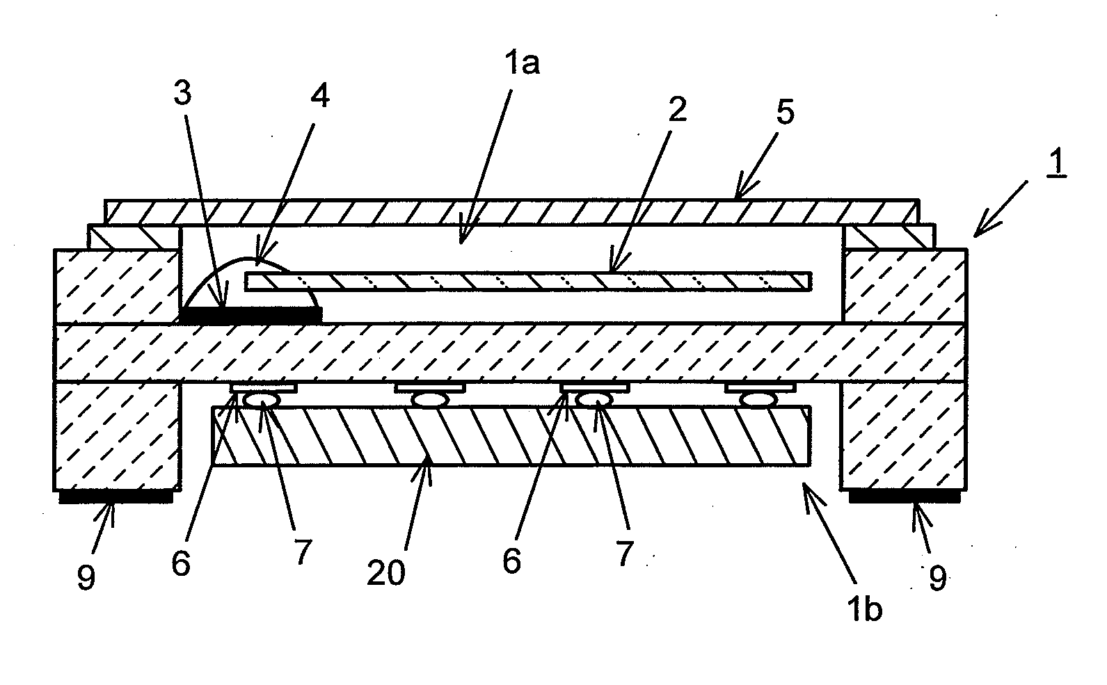
  • Crystal oscillator
  • Crystal oscillator
  • Crystal oscillator

Examples


Embodiment Construction

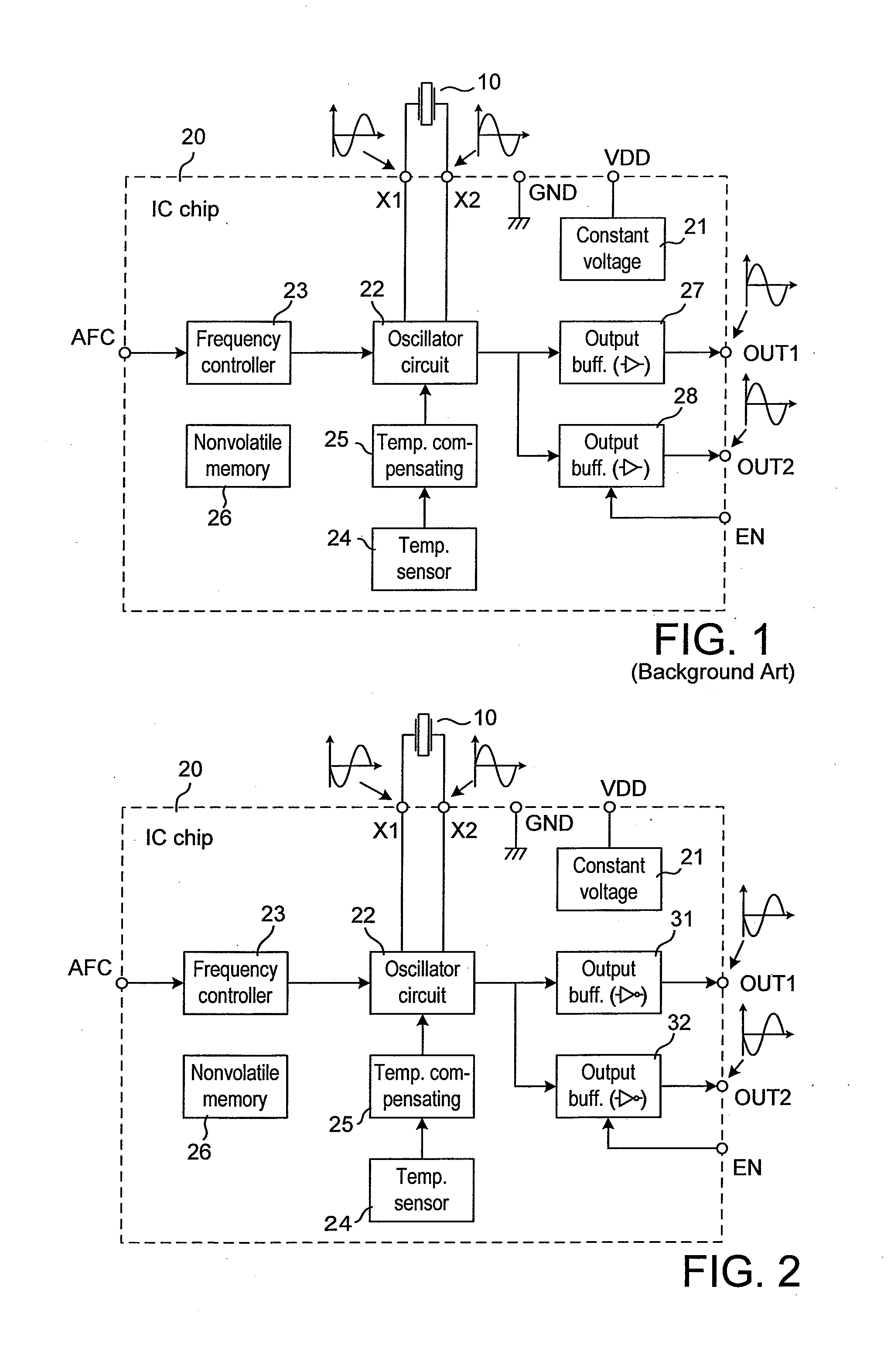
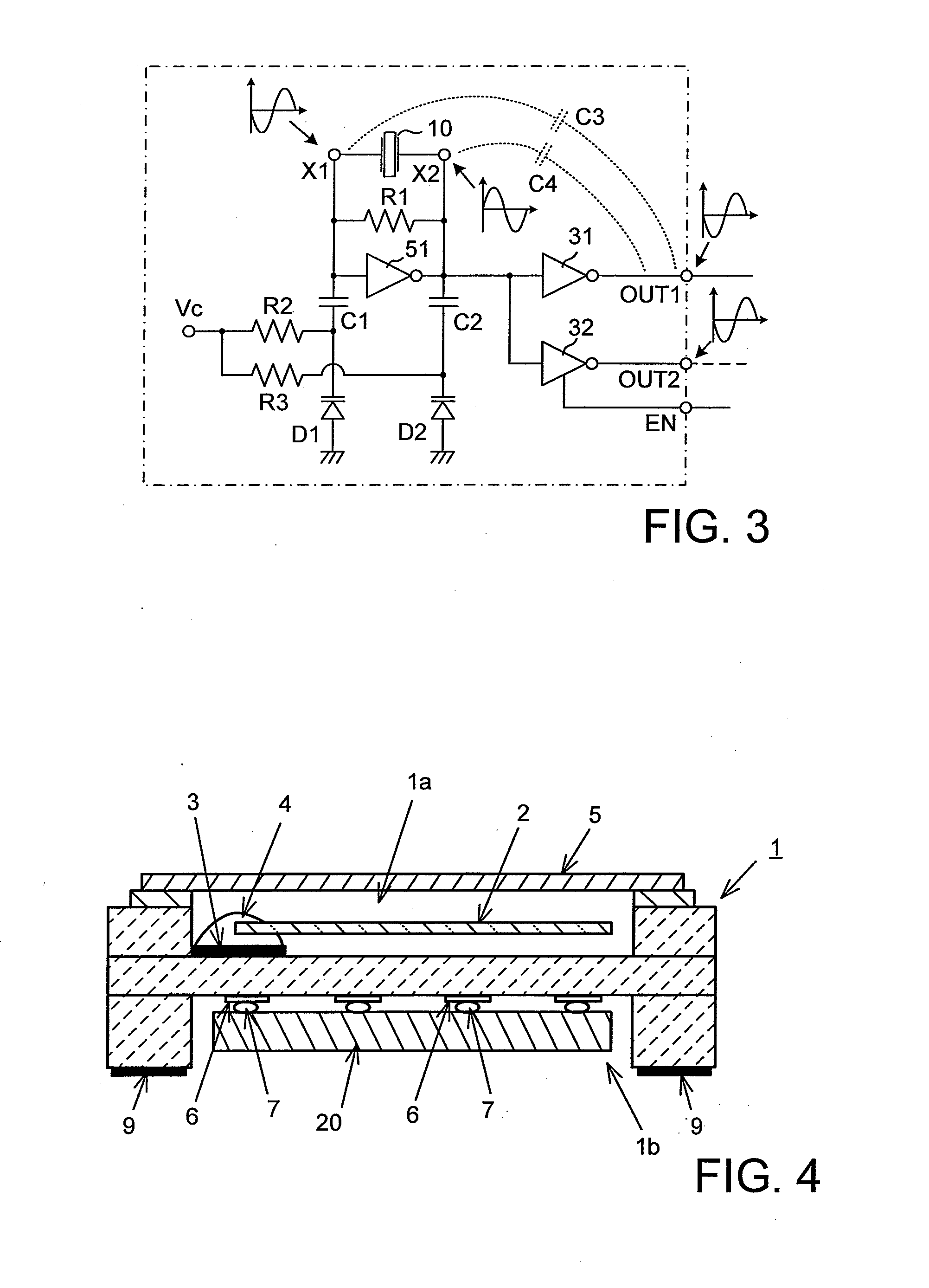
[0023]In the figures with which description will be made below, parts and elements identical to those in FIG. 1 are assigned with identical reference numerals, and description thereof is simplified or omitted.

[0024]A quartz crystal oscillator according to an embodiment of the present invention shown in FIG. 2 is configured as a TCXO, as with that shown in FIG. 1. This oscillator is configured by integrating crystal unit 10 and IC chip 20 into a package component. For instance, a crystal unit using an AT-cut quartz crystal blank is employed as crystal unit 10. Various configurations can be used for integrating crystal unit 10 and IC chip 20. These configurations may be: a configuration in which a package including an IC chip is attached to a crystal unit which is configured by encapsulating a crystal blank in a container body; a configuration hermetically encapsulating a crystal blank, which functions as a crystal blank, together with an IC chip in one recess provided in a container ...


PUM


Abstract

A crystal oscillator is configured by accommodating a crystal blank that functions as a crystal unit and an IC chip that includes at least an oscillator circuit using the crystal blank into a container in an integrated manner. In the IC chip, the oscillator circuit is connected to the crystal unit via a pair of crystal connecting terminals, an output from the oscillator circuit is supplied to a plurality of output buffers. In relation to the crystal connecting terminal having a phase opposite to that of an output from the on / off controllable output buffer, an output terminal of this output buffer is disposed farther than an output terminal of the output buffer that is not subjected to the on / off control.

Description

BACKGROUND OF THE INVENTION[0001]1. Field of the Invention[0002]The present invention relates to a quartz crystal oscillator that includes a quartz crystal unit and an IC (integrated circuit) chip integrating an oscillator circuit using the crystal unit in one component, and more specifically, to a crystal oscillator with improved stability of oscillation frequency.[0003]2. Description of the Related Arts[0004]The crystal oscillator configured by combining the crystal unit and the IC chip integrating the oscillator circuit using the crystal unit into a single package component can easily adopt a surface mount configuration, and is widely incorporated as a reference source of frequency and time in a mobile electronic device, for instance, typified by a mobile phone.[0005]In the crystal oscillator, the electronic circuit integrated in the IC chip is not limited to an oscillator circuit. Instead, for instance, an electronic circuit, such as a temperature compensating circuit, can be in...

Claims


Application Information

Patent Timeline
IPC IPC(8): H05K7/00
CPCH03B5/364H03L1/028H03B5/36H03L1/04H03L1/022H03B7/06H03B2201/0208
Inventor ASAMURA, FUMIO
Owner NIHON DEMPA KOGYO CO LTD
Learn More