
Time-domain voltage comparator for analog-to-digital converter

a voltage comparator and time-domain technology, applied in the field of analog-to-digital converters, can solve the problems of inability to ensure the stability of the analog-to-digital converter, the inability to reduce the voltage of the supply power and offset, and the marked degradation of the reliability of the analog circuit, so as to achieve the effect of reducing offset and improving insensitivity to the thermal noise of transistors

Inactive Publication Date: 2012-07-12
POSTECH ACAD IND FOUND
View PDF3 Cites 24 Cited by
  • Summary
  • Abstract
  • Description
  • Claims
  • Application Information

AI Technical Summary

Benefits of technology

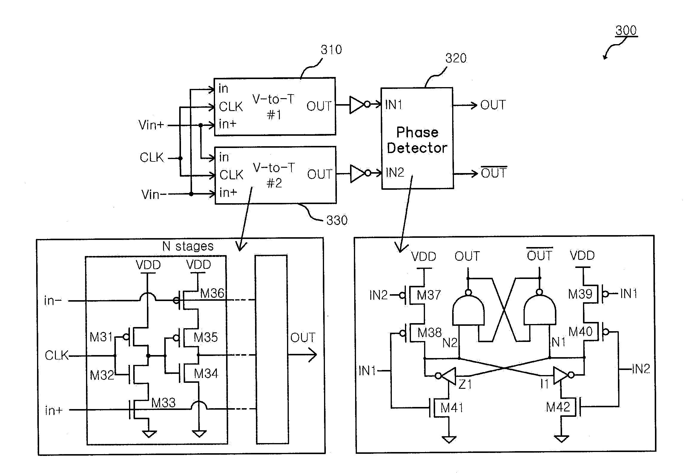
[0027]Another object of the present invention is to provide a time-domain voltage comparator for an analog-to-digital converter which uses a plurality of time delay units in the course of converting voltage differences into time differences so that insensitivity to the thermal noise of transistors is improved when compared to the conventional comparator and an offset is decreased.

Problems solved by technology

In particular, in the case of application fields, such as a portable terminal or a wireless sensor network, in which power supply depends on a battery and therefore available energy is extremely limited, it is essential to decrease a supply voltage and minimize power consumption.
In this regard, if the supply voltage is decreased, the reliability of an analog circuit markedly deteriorates when compared to a digital circuit, and therefore, a problem is caused in that the stable operation of an analog-to-digital converter cannot be ensured.
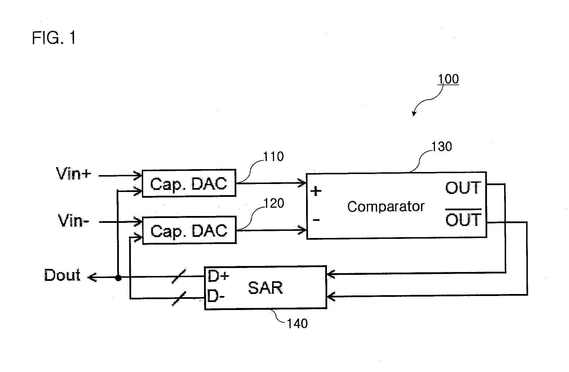
While this kind of comparator has been introduced on the ISSCC in 2008, excellent results have not been obtained with respect to reducing a voltage of supply power and an offset.
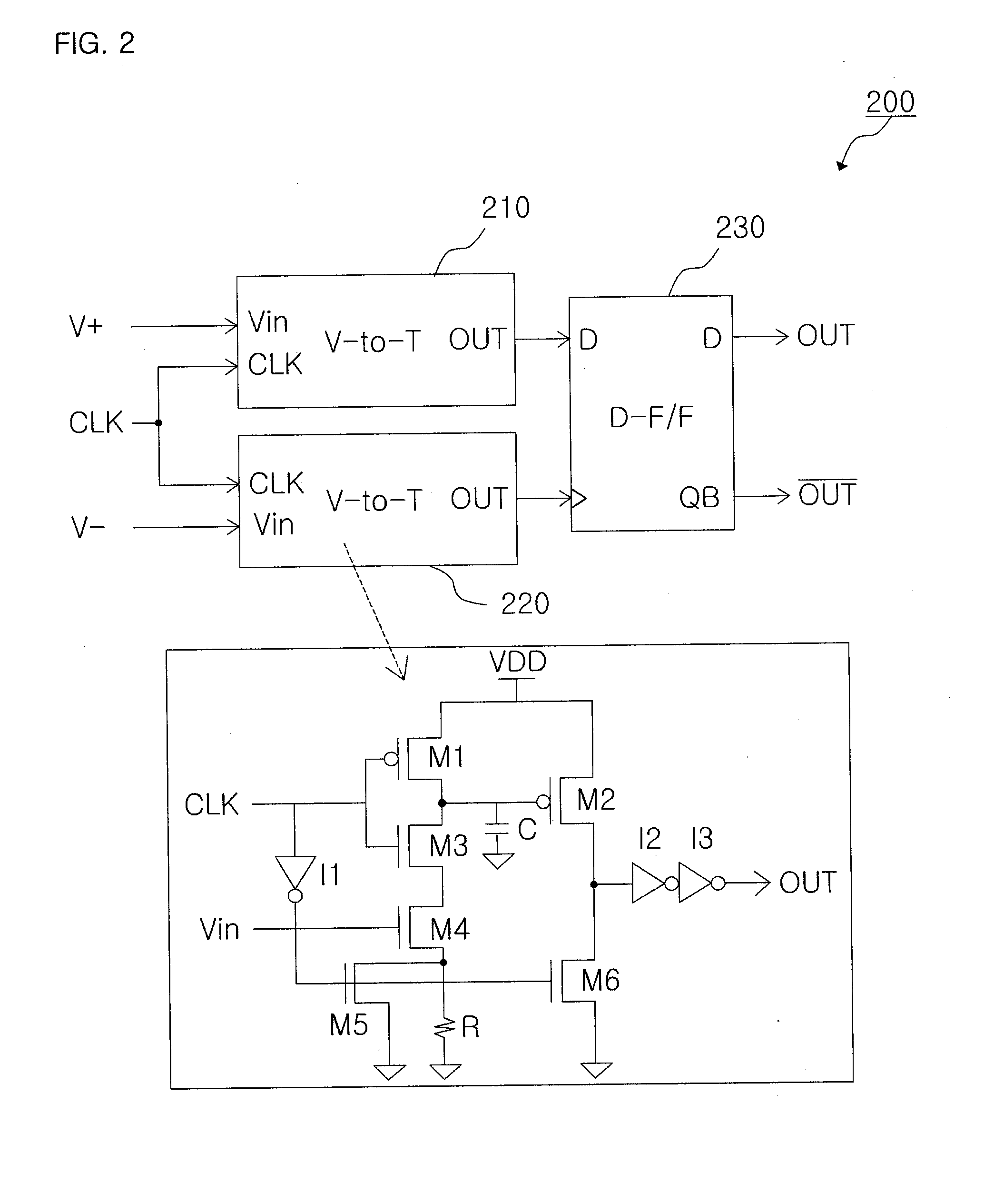
If a high input voltage Vin is applied, the NMOS M4 is sufficiently turned on to have a low resistance value, and if a low input voltage Vin is applied, the NMOS M4 is insufficiently turned on to have a high resistance value.
However, this type of comparator has two problems as described below, in the light of an offset.
First, if matching of the two voltage-to-time converts is not precisely implemented, even though the same input voltage is supplied, times during which the outputs transit become different, and due to this fact, an offset occurs.
Second, even when matching of the two voltage-to-time converts is precisely implemented, an offset is likely to occur due to a set-up time and a hold time as the inherent characteristics of the D flip-flop.

Method used


Image

  • Time-domain voltage comparator for analog-to-digital converter
  • Time-domain voltage comparator for analog-to-digital converter
  • Time-domain voltage comparator for analog-to-digital converter

Examples


Embodiment Construction

[0041]Reference will now be made in greater detail to preferred embodiments of the invention, examples of which are illustrated in the accompanying drawings. Wherever possible, the same reference numerals will be used throughout the drawings and the description to refer to the same or like parts.

[0042]The basic principle of the present invention resides in that a plurality of time delay cells are provided so that match between voltage-to-time converters is improved and analog elements (such as capacitors and resistors) are removed so that an area can be efficiently decreased.

[0043]In the following description of the present invention, detailed explanations of known functions and configurations associated herewith will be omitted when they can make the subject matter of the present invention rather unclear.

[0044]FIG. 3 is a block diagram illustrating the configuration of a time-domain voltage comparator for an analog-to-digital converter in accordance with an embodiment of the presen...


PUM


Abstract

A time-domain voltage comparator for an analog-to-digital converter includes a first voltage-to-time converter configured to be connected in series with at least one time delay cell and convert an input voltage into time information; a second voltage-to-time converter configured to be connected in series with at least one time delay cell and convert an input voltage into time information; and a phase comparator configured to determine a difference between times outputted from the first voltage-to-time converter and the second voltage-to-time converter.

Description

BACKGROUND OF THE INVENTION[0001]1. Field of the Invention[0002]The present invention relates to an analog-to-digital converter, and more particularly, to a time-domain voltage comparator for an analog-to-digital converter which can convert voltage differences into time differences.[0003]2. Description of the Related Art[0004]In general, an analog-to-digital converter (ADC) is a circuit for converting an analog signal into a digital signal and is used as one of essential blocks not only in the field of wireless communication but also in all the fields of signal processing.[0005]In particular, in the case of application fields, such as a portable terminal or a wireless sensor network, in which power supply depends on a battery and therefore available energy is extremely limited, it is essential to decrease a supply voltage and minimize power consumption.[0006]In this regard, if the supply voltage is decreased, the reliability of an analog circuit markedly deteriorates when compared t...

Claims


Application Information

Patent Timeline
IPC IPC(8): H03D13/00
CPCH03M1/50H03M1/0682H03M1/12H03M1/64
Inventor LEE, SEON KYOOSIM, JAE YOON
Owner POSTECH ACAD IND FOUND
Learn More