Gas detecting system and method therof

Inactive Publication Date: 2012-07-05
GETAC TECH CORP
View PDF5 Cites 8 Cited by
  • Summary
  • Abstract
  • Description
  • Claims
  • Application Information

AI Technical Summary

Benefits of technology

[0013]The gas detecting system of the present invention can be used for detecting a gas in an external environment. With the design of electrical connection between the joining port and the connection port, on one hand, the computer device can be effectively used for managing and controlling the operation of the gas detecting system and the running of the gas detection; and on the other hand, the fabricating cost of the gas measuring device can be effectively reduced. Through the selection of the light source and the sensor, the gas detecting system can detect multiple gases simultaneously. Moreover, with the arrangement of the alarm, when the concentration of the gas detected is excessively high, the alarm can warn the user that the external environment may be dangerous.

Problems solved by technology

When the result signal is a dangerous state, the alarm generates a sound signal.

Method used


Image

  • Gas detecting system and method therof
  • Gas detecting system and method therof
  • Gas detecting system and method therof

Examples


fifth embodiment

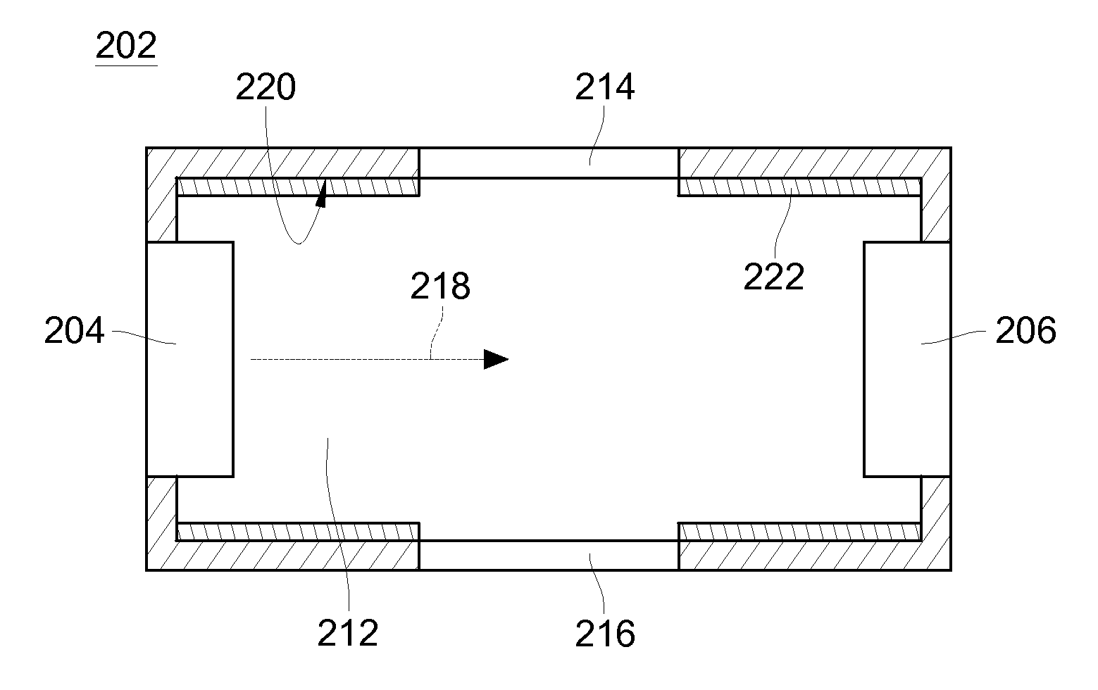
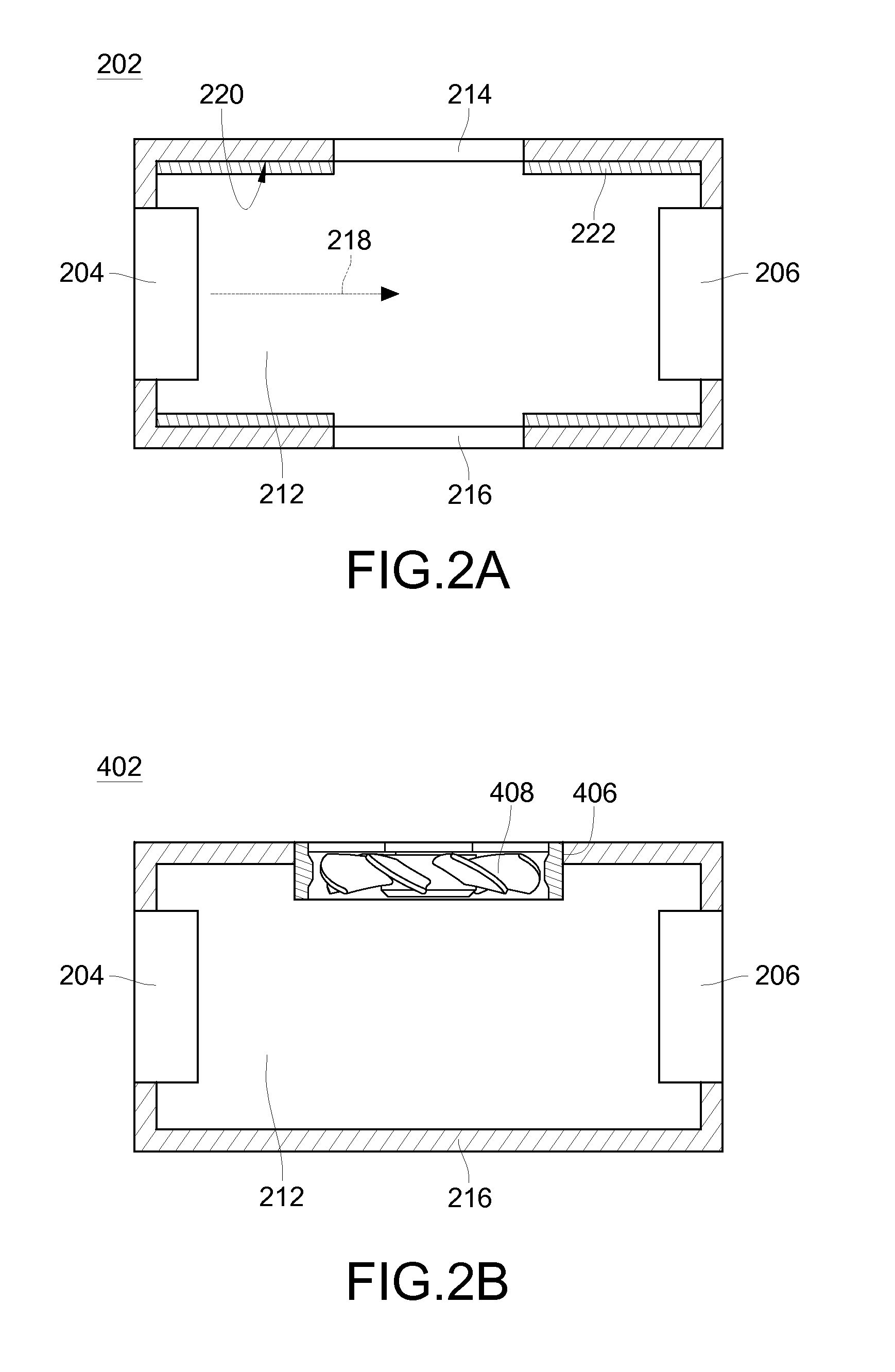
[0032]The gas detecting system 100 of the above embodiment is used for detecting a gas from the external environment that is capable of flowing into and out from the air cell, but the above embodiment is not intended to limit the present invention. That is to say, the gas detecting system 100 may also be used for detecting a gas in a gas container 40. FIG. 2E is a schematic cross-sectional structural view of the chamber of the present invention. In this embodiment, a gas to be detected may be firstly filled into the gas container 40, and the gas will not flow out from the gas container 40. Next, the gas container 40 is placed in the chamber 202 through the opening 214. It should be noted that, the gas container 40 may be made of, but is not limited to, a light transmissive material, and the gas of the external environment cannot enter the air cell 212 after the gas container 40 is placed in the chamber 202, so as to prevent the gas of the external environment from influencing the de...

first embodiment

[0034]FIG. 3 is a schematic flow chart of a gas detecting method of the present invention applied to a gas detecting system. Referring to FIG. 2 and FIG. 3, in this embodiment, the gas detecting method comprises the following steps.

[0035]In Step 602, at least one control signal is generated to a processor, and the processor controls a light source to emit light, wherein the light source is disposed in a chamber.

[0036]In Step 604, a sensor receives the light and generates a sensing signal, wherein the sensor is disposed in the chamber and is used for receiving the light emitted by the light source correspondingly.

[0037]In Step 606, the processor receives the sensing signal and performs a processing procedure to output a characteristic value.

[0038]In Step 608, the characteristic value is received through a joining port and a result signal is generated through an operation procedure.

[0039]Before Step 602 is performed, the air cell 212 may be communicated with an external environment th...


PUM


Abstract

A gas detecting system includes a gas measuring device and a computer device. The gas measuring device includes a chamber, at least one light source, at least one sensor, a processor, and a connection port. The computer device includes a joining port and an arithmetic unit, and the connection port is electrically connected to the joining port. The arithmetic unit outputs at least one control signal after a control procedure. The processor controls the light source disposed in the chamber to emit light which passes through an air cell of the chamber according to the control signal such that the sensor disposed in the chamber outputs a sensing signal to the processor. The processor outputs a characteristic value to the computer device according to the sensing signal. Therefore, the computer device can control and start the gas measuring device to perform gas detection through outputting the control signal.

Description

BACKGROUND OF THE INVENTION[0001]1. Field of the Invention[0002]The present invention relates to a gas detecting system and method thereof, and more particularly to a gas detecting system and method thereof capable of controlling and starting gas detection in multiple modes.[0003]2. Related Art[0004]In recent years, with the rapid development of economy, the living environment of human beings is gradually contaminated. However, with the rise of the awareness of environmental protection and the increasing demands for the quality of life of people, how to effectively control hazardous substances in the living environment of human beings becomes an important issue.[0005]Generally, gas detecting methods are mainly categorized into four types. The first gas detecting method is the use of semiconductor sensors. However, due to the disadvantages of high power consumption of the semiconductor sensors, it is difficult to develop the semiconductor sensors. The second gas detecting method is t...

Claims


Application Information

Patent Timeline
IPC IPC(8): G06F19/00
CPCG01N21/33G01N21/61G01N21/3504
Inventor WANG, HSIEN-YU
Owner GETAC TECH CORP
Why Eureka
Try Eureka