Coated article and method for making same

Inactive Publication Date: 2012-07-05
HONG FU JIN PRECISION IND (SHENZHEN) CO LTD +1
View PDF3 Cites 5 Cited by
  • Summary
  • Abstract
  • Description
  • Claims
  • Application Information

AI Technical Summary

Benefits of technology

[0005]Good wetting property is important to solid surfaces. The solid surface, if being hydrophobic, requires that the water contact angle of the solid surface to be greater than 90°. To obtain a hydrophobic surface, the solid surface is usually coated with an organic hydrophobic layer. The organic hydrophobic layer is generally made of polymer material including fluorine and / or silicon. However, organic hydrophobic materials have shortcomings, such as low hardness, poor wear resistance and low heat-resistance temperature, which limits further applications of the organic hydrophobic materials.

Problems solved by technology

However, organic hydrophobic materials have shortcomings, such as low hardness, poor wear resistance and low heat-resistance temperature, which limits further applications of the organic hydrophobic materials.

Method used


Image

  • Coated article and method for making same
  • Coated article and method for making same
  • Coated article and method for making same

Examples


example 1

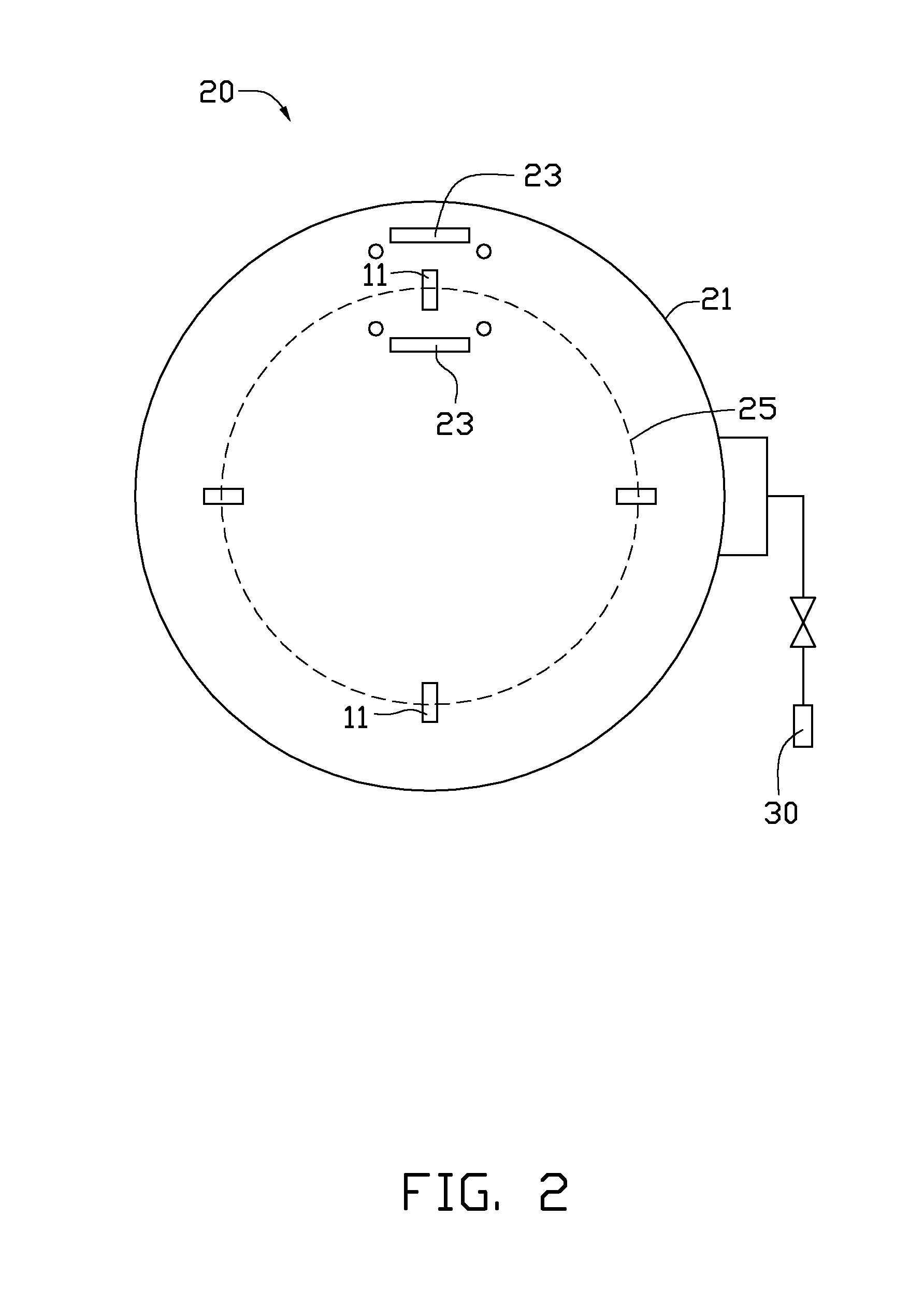
[0023]The vacuum sputtering device 20 used in example 1 was a medium frequency magnetron sputtering device (model No. SM-1100H) manufactured by South Innovative Vacuum Technology Co., Ltd. located in Shenzhen, China.

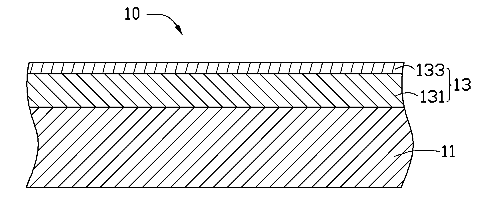
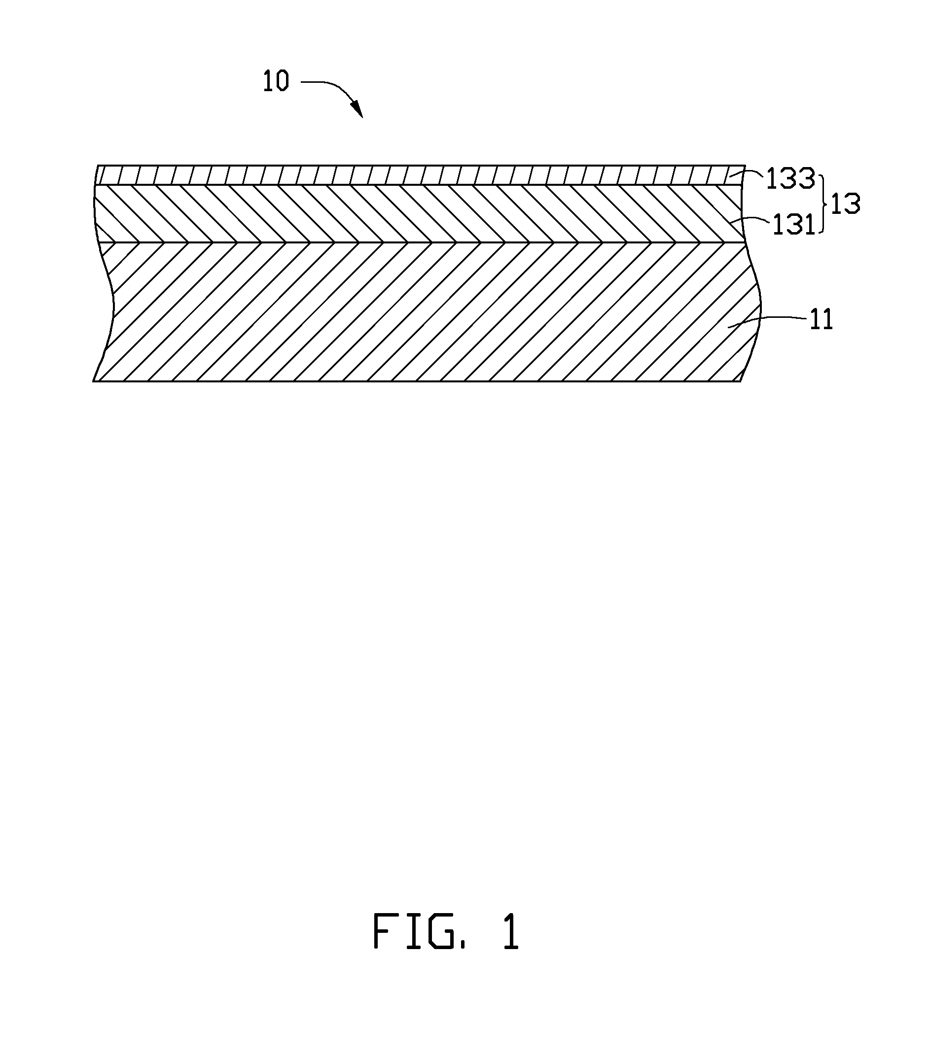
[0024]The substrate 11 was made of glass.

[0025]Plasma cleaning: Ar was fed into the vacuum chamber 21 at a flow rate of about 500 sccm. A negative bias voltage of −150 V was applied to the substrate 11. Plasma cleaning of the substrate 11 took about 8 min.

[0026]Sputtering to form the preliminary layer: The vacuum chamber 21 was heated to about 300° C. Ar was fed into the vacuum chamber 21 at a flow rate of about 320 sccm. Ammonia gas was fed into the vacuum chamber 21 at a flow rate of about 280 sccm. The power of the graphite targets 23 was 10 kw and a negative bias voltage of −180 V was applied to the substrate 11. The depositing of the preliminary layer took 40 min. The preliminary layer had a thickness of about 450 nm.

[0027]Fluorination treatment: The temperature in ...

example 2

[0029]The vacuum sputtering device 20 used in example 2 was the same in example 1.

[0030]The substrate 11 was made of stainless steel.

[0031]Plasma cleaning: Ar was fed into the vacuum chamber 21 at a flow rate of about 500 sccm. A negative bias voltage of −180 V was applied to the substrate 11. The plasma cleaning of the substrate 11 took about 10 min.

[0032]Sputtering to form the preliminary layer: The vacuum chamber 21 was heated to about 330° C. Ar was fed into the vacuum chamber 21 at a flow rate of about 300 sccm. Ammonia gas was fed into the vacuum chamber 21 at a flow rate of about 220 sccm. The power of the graphite targets 23 was 9 kw and a negative bias voltage of −220 V was applied to the substrate 11. The depositing of the preliminary layer took 55 min. The preliminary layer had a thickness of about 612 nm.

[0033]Fluorination treatment: The temperature in the furnace was maintained at about 120° C. The CF4 gas pressure in the furnace was about 98 Pa. The radiofrequency powe...


PUM

PropertyMeasurementUnit
Temperatureaaaaaaaaaa

Abstract

A coated article is provided. The coated article includes a substrate, a hydrophobic layer formed on the substrate. The hydrophobic layer includes a first layer portion formed on the substrate and a second layer portion formed on the first layer portion, the first layer portion is a CNy layer, the second layer portion is a CNxFz layer, wherein 1≦y≦3, 1≦x≦3, 1≦z≦4. The water contact angle of the hydrophobic layer is more than 110°. The hydrophobic layer has a good chemical stability, high-temperature resistance and a good abrasion resistance, which effectively extends the use time of the coated article. A method for making the coated article is also described there.

Description

CROSS-REFERENCE TO RELATED APPLICATIONS[0001]The present application is related to co-pending U.S. patent applications (Attorney Docket No. US35723), entitled “COATED ARTICLE AND METHOD FOR MAKING SAME”, by Zhang et al. These applications have the same assignee as the present application and have been concurrently filed herewith. The above-identified applications are incorporated herein by reference.BACKGROUND[0002]1. Technical Field[0003]The present disclosure relates to coated articles, particularly to coated articles with hydrophobic effect and a method for making the coated articles.[0004]2. Description of Related Art[0005]Good wetting property is important to solid surfaces. The solid surface, if being hydrophobic, requires that the water contact angle of the solid surface to be greater than 90°. To obtain a hydrophobic surface, the solid surface is usually coated with an organic hydrophobic layer. The organic hydrophobic layer is generally made of polymer material including fl...

Claims


Application Information

Patent Timeline
IPC IPC(8): B32B3/00C23C14/06C23C14/35B32B17/06B32B15/04
CPCC23C14/0057C23C14/022Y10T428/265C23C14/345C23C14/35C23C14/0658Y10T428/31678
Inventor CHANG, HSIN-PEICHEN, WEN-RONGCHIANG, HUANN-WUCHEN, CHENG-SHILI, CONG
Owner HONG FU JIN PRECISION IND (SHENZHEN) CO LTD
Why Eureka
Try Eureka