
Universal laminoplasty implant

Inactive Publication Date: 2012-06-28
KHANNA ROHIT
View PDF26 Cites 48 Cited by
  • Summary
  • Abstract
  • Description
  • Claims
  • Application Information

AI Technical Summary

Benefits of technology

[0006]The present invention relates a laminar fusion and fixation system following either open door or double door laminoplasty technique. This system with the spacer and plate reduces surgical time and simplifies laminar fixation and fusion if needed after laminoplasty.
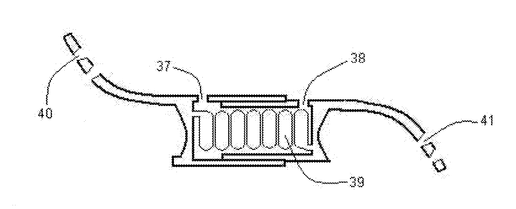
[0011]The telescopic spacer allows the extent of the laminar displacement to be adjustable by increasing or decreasing the spacer length after lamina fixation device has been implanted. Henceforth, it avoids the need for different size implants as one implant can be adjusted to fit all variations in spinal anatomy as well as the extent of the spinal canal decompression desired. The spacer telescopic components can also contain an engaging mechanism to interlock with each other through ratchet teeth to maintain the adjusted length. Alternative spacer telescopic engaging mechanisms can include screws, ridges, hooks, recesses, or a ball and socket mechanism.
[0015]A minimally invasive approach is undertaken with small incisions and serial dilation of the soft tissue along with splitting of the paraspinal muscles from the skin to the spine. A tubular port or any other shape retractor is then placed to maintain the exposure. The drilling of the lamina and if needed the spinous process is undertaken with this exposure using either an endoscope or microscope magnification and subsequently the lamina are displaced to widen the spinal canal. A laminoplasty implant is then placed and secured to the lamina and facet. Due to the small exposure, a laminoplasty implant that can contract to allow placement in the spine and then expand to the position desired after implant is ideal for this approach. The telescopic spacers described herein are ideal for this approach. The tubular port is then removed and the skin incision closed. Intra-operative x-rays or a navigation system can be used to localize the spine level and confirm correct implant placement.Another variation of the open door laminoplasty is the expansive laminoplasty most suited for the thoracolumbar spine. In this method, the lamina on either side at the junction of the facets are drilled and opened. A lateral spinal canal recess decompression and / or foraminotomy is undertaken and the lamina replaced with the spacer construct on both sides between the displaced lamina and facets. The present invention relates a laminar fusion and fixation system following laminoplasty. This system with the telescopic spring spacer reduces surgical time and simplifies laminar fixation after laminoplasty.
[0017]In another embodiment of the bone spacer, the edges have a superior cuff or shoulder that allows securement against the lamina and facet on both sides as well prevent migration of the spacer into the spinal canal. The spacer can also be resorbable and made of hydroxyapatite or similar absorbable material which is eventually resorbed and / or replaced with autologous bone during the fusion process.
[0019]In another embodiment the allograft bone or resorbable graft and plate are constructed as a unit with the bone graft / spacer attached to the plate in the middle through either screws or an adhesive material.In another embodiment, the bone graft and plate are designed for laminar fusion and fixation following double door laminoplasty. The bone graft or spacer in the middle allows for laminar fusion in the decompressed position with the plate design bent on either end securing the spacer to the lamina and facet.
[0024]The telescopic component of the fixation system allows the two portions of the plate to slide into or away from each other thereby adjusting the spacer length and provides for laminar displacement after the device has been implanted. This avoids the need for manually displacing the lamina during surgery at which time with the traditional procedure, several spacer implant sizes are tested to find the right size that conforms to the patient's spine anatomy.

Problems solved by technology

Cervical stenosis with spinal cord compression and consequent myelopathy is a very common problem encountered by the spine surgeon.
The main drawback of this technique is the increased time and complexity of the procedure as well as the risk of pseudoarthrosis and accelerated degeneration at the levels above and below the fusion.
The drawback of a simple laminectomy is the risk of late clinical deterioration from either kyphosis, instability, or post-laminectomy scar formation.
Laminectomy with facet fusion decreases the risk of kyphosis but it also decreases the range of motion in the spine and increases the risk of accelerated degeneration at the levels above and below the fusion.

Method used


Image

  • Universal laminoplasty implant
  • Universal laminoplasty implant
  • Universal laminoplasty implant

Examples


Embodiment Construction

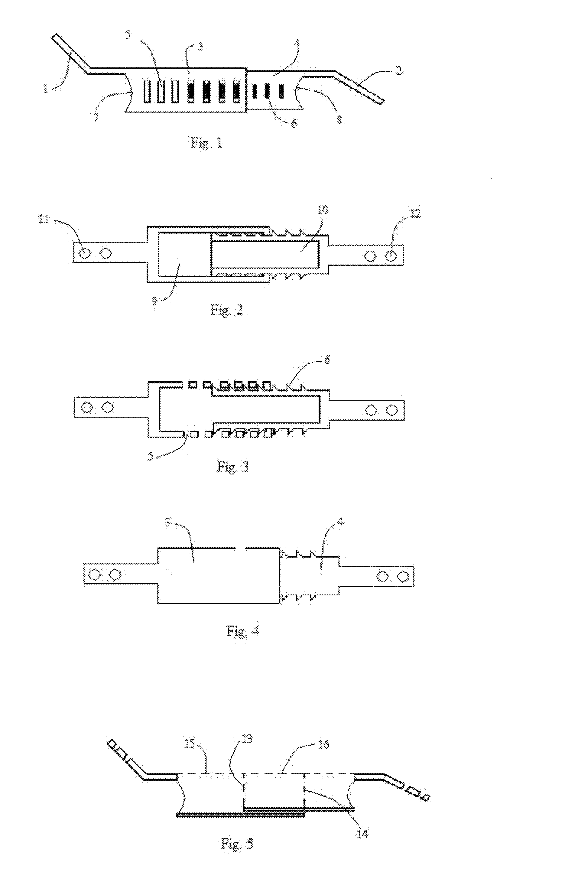
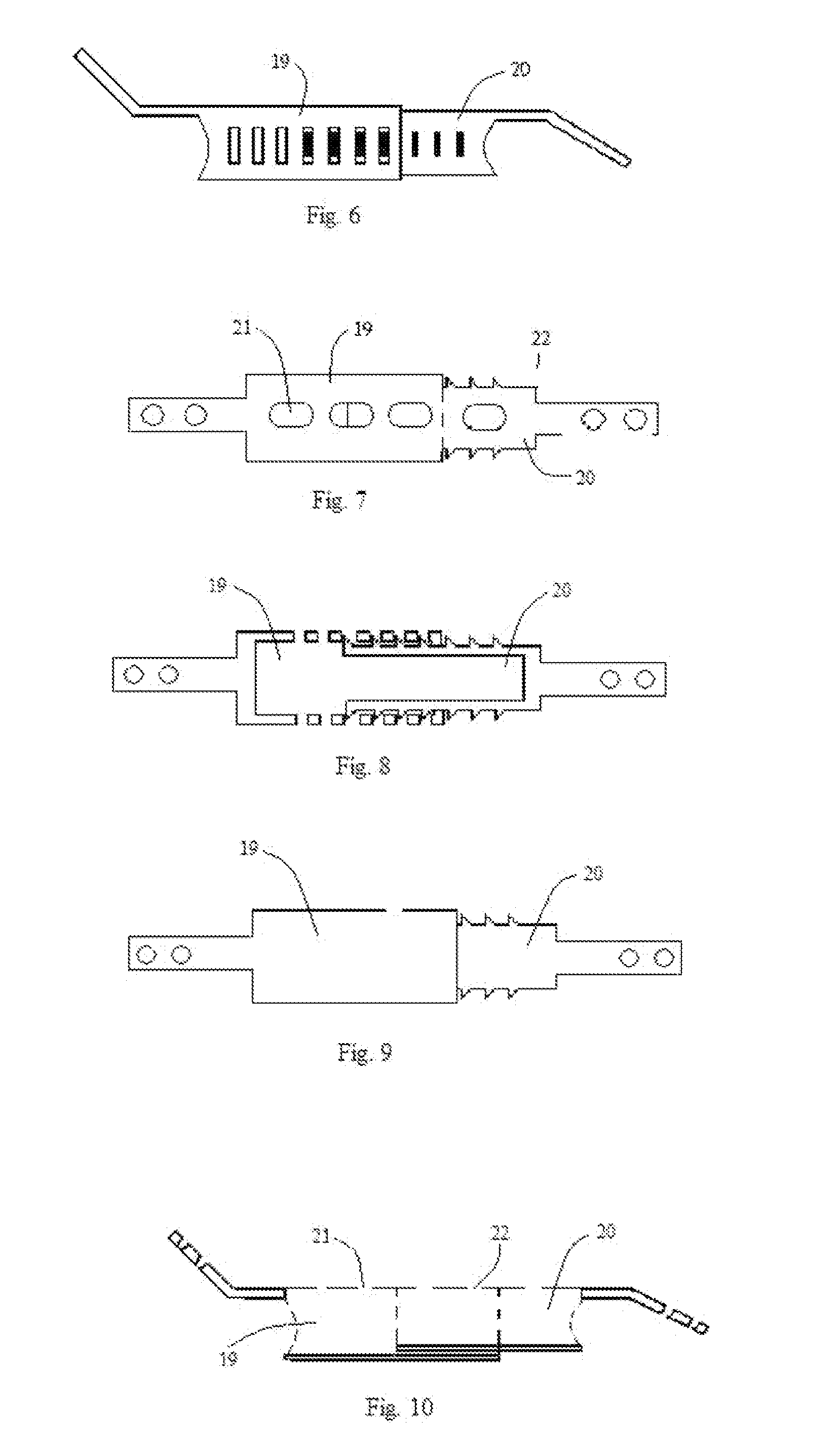
[0143]The present invention describes a device and method for fixation of lamina following a laminoplasty. The laminoplasty device as shown in FIGS. 1-5 comprises a spacer 3 with an extension 1 and a spacer 4 with an extension 2. The spacers 3 and 4 are telescopically engaged to each other with ridges or ratchet teeth 6 on the spacer 4 with the recesses 5 in the spacer 3. The spacers 3 and 4 are hollow with open ends 7 and 8 respectively. The spacer 3 and 4 walls are open at the top 15 and 16 and ends 7, 14 and 8, 13 respectively to allow packing of the hollow spacers after or before implantation with bone fusion material to fuse the lamina with the facet. Bone fusion material can comprise of autograft bone, allograft bone, xenograft bone, demineralized bone matrix, bone morphogenic protein, hydroxyapatite, and other bone fusion extenders. The solid floors 9 and 10 face the spinal canal and prevent the bone fusion material from migrating into the spinal canal. The extension 1 is ang...


PUM


Abstract

The present invention relates various embodiments of a laminoplasty implant comprising a telescopic spacer configured to attach to the vertebra and adjust the space between two cut portions of a vertebra.

Description

[0001]Related U.S. Application Data: Continuation-in-part of application Ser. No. 10 / 299,624 filed on Nov. 19, 2002 now U.S. Pat. No. 6,660,007, which is a continuation of application No. Ser. 10 / 035,281 filed on Jan. 3, 2002BACKGROUND OF THE INVENTION[0002]Cervical stenosis with spinal cord compression and consequent myelopathy is a very common problem encountered by the spine surgeon. The usual cause of multilevel cervical stenosis is spondylosis and / or ossification of the posterior longitudinal ligament. Surgical decompression either through an anterior or posterior approach can be undertaken.An anterior approach usually involves multilevel corpectomy with fusion and stabilization. The main drawback of this technique is the increased time and complexity of the procedure as well as the risk of pseudoarthrosis and accelerated degeneration at the levels above and below the fusion.[0003]A posterior approach has traditionally involved a simple laminectomy, laminectomy with facet fusio...

Claims


Application Information

Patent Timeline
IPC IPC(8): A61F2/44
CPCA61B2017/00004A61B17/7071
Inventor KHANNA, ROHIT
Owner KHANNA ROHIT
Learn More