
Method and apparatus for measurement and control of magnetic particle concentration in a magnetorheological fluid

a technology of magnetorheological fluid and concentration method, which is applied in the direction of grinding machine components, manufacturing tools, lapping machines, etc., can solve the problems of accelerating wear and tear of the delivery system components, affecting the productivity and flexibility of technology, and affecting the cost of such a delivery system. significant and the total cost of the mr finishing system may constitute up to a quarter of the total cost,

Active Publication Date: 2012-06-28
QED TECH INT LLC
View PDF5 Cites 10 Cited by
  • Summary
  • Abstract
  • Description
  • Claims
  • Application Information

AI Technical Summary

Benefits of technology

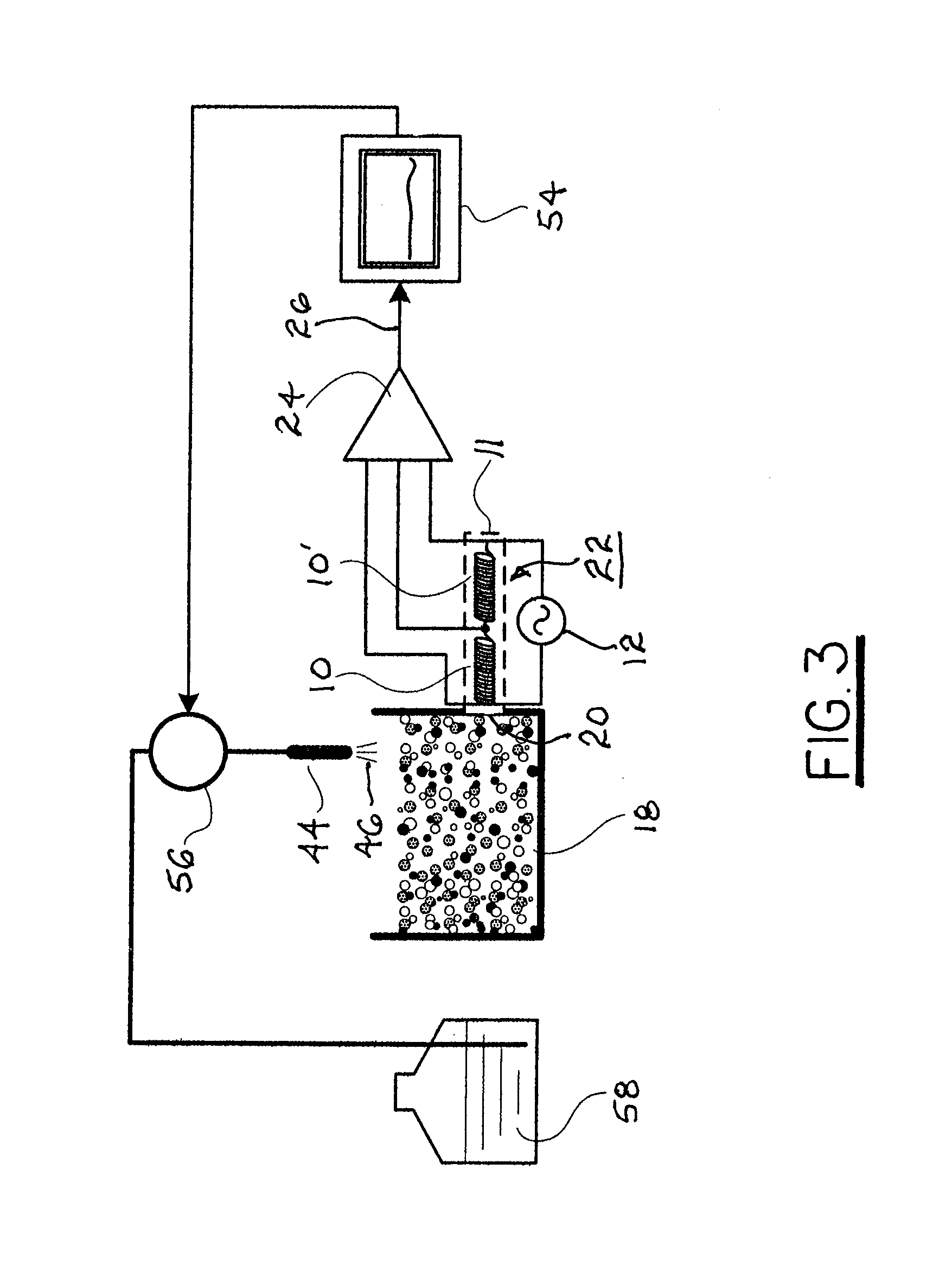
[0020]The system may also contain means to compensate for thermal variations in circuit impedance. For example, the sensor may comprise two identical coils which are in thermal contact: a sense coil and a reference coil. They are driven by a high-frequency sine-wave excitation, and their differential impedance is measured using a sensitive demodulator. Differencing the two coils' outputs provides a sensitive way to measure the MR fluid permeability (which is proportional to concentration of magnetic particles), while cancelling out variations caused by temperature. A signal from the sensor provides input to a feedback controller that causes a water dispensing subsystem to add a calculated amount of water to the MR fluid to restore the fluid to a desired particle concentration.

Problems solved by technology

Cost of such a delivery system is significant and may constitute up to quarter of the total cost of the MR finishing system.
Recharging of the delivery system is a time-consuming process, requiring complete disassembling, cleaning of all components, re-assembly, and breaking in after charging with a fresh fluid, which lengthy procedure negatively affects productivity and flexibility of technology.
Such continuous recirculation results in accelerated wear and tear of delivery system components and consumption of extra energy.
MR fluid flow rate instability (pulsations) in the delivery system due to any of several causes results in unstable removal rate and errors on the substrate surface.
This limits selection of fluid components and restricts fluid composition, for example, for greater solids concentration required for enhancement of the removal rate.

Method used


Image

  • Method and apparatus for measurement and control of magnetic particle concentration in a magnetorheological fluid
  • Method and apparatus for measurement and control of magnetic particle concentration in a magnetorheological fluid
  • Method and apparatus for measurement and control of magnetic particle concentration in a magnetorheological fluid

Examples


Embodiment Construction

[0028]The principle of measurement of the magnetic permeability of a material (MR Fluid) and of an apparatus in accordance with the present invention is as follows.

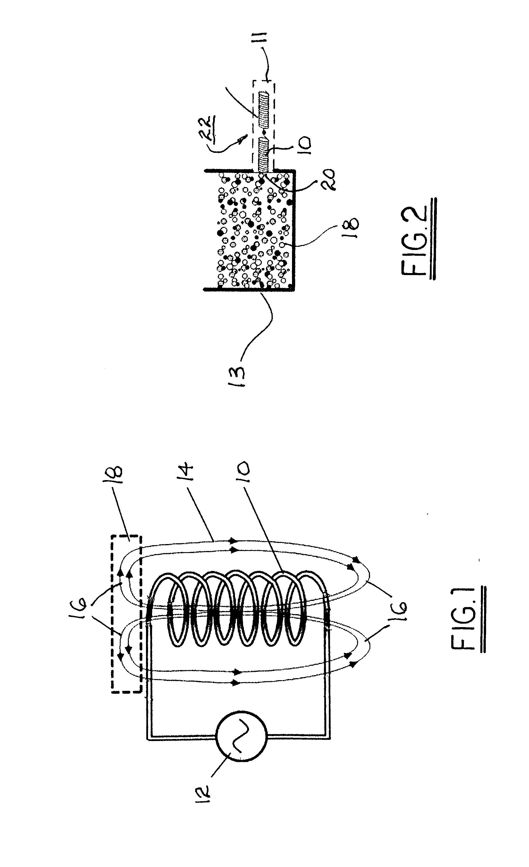
[0029]Referring to FIGS. 1 and 2, a wire coil 10 is connected to an AC voltage generator 12, resulting in a magnetic field 14 in known fashion. Magnetic field 14 includes regions of so-called fringing fields 16 beyond each end of coil 10. A sample of a magnetic material 18 such as MR fluid in which magnetic permeability is to be measured is placed next to coil 10 within fringing field 16. When a voltage is applied to coil 10, a magnetic circuit is formed to conduct a magnetic flux generated by the coil. The circuit consists of two main components: coil 10 and sample 18. Applying Ampere's circuital law to the circuit and assuming that the leakage flux is negligible we see that:

NI=Hclc+Hsls   (1)

where NI is coil magnetomotance (N is number of turns and I is the current); the subscript c refers to the coil and s to the sampl...


PUM

PropertyMeasurementUnit
magnetic flux fieldaaaaaaaaaa
concentrationaaaaaaaaaa
voltageaaaaaaaaaa

Abstract

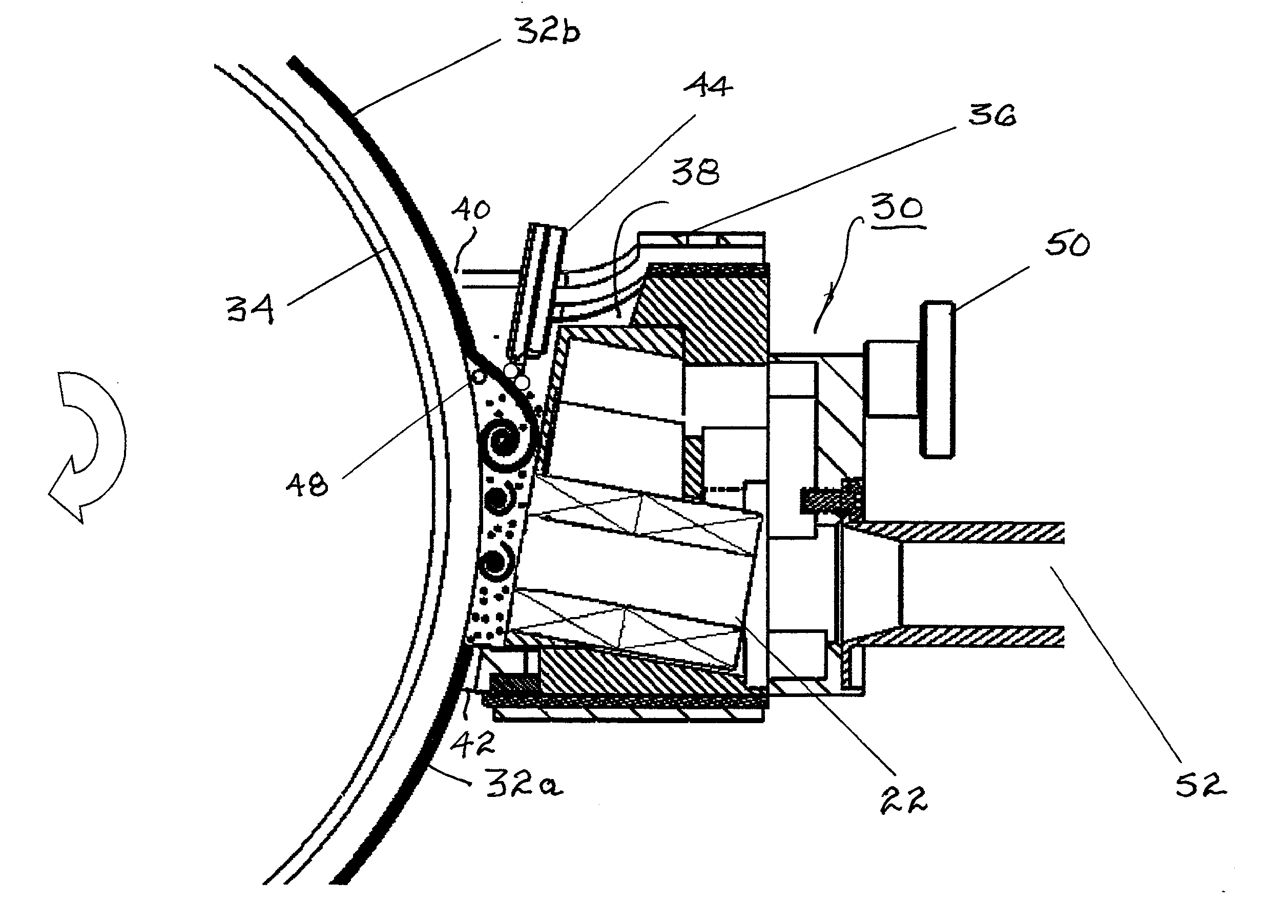
A system for sensing and controlling concentration of magnetic particles in magnetorheological fluid comprising a wire coil and an AC voltage generator that, when energized, creates a magnetic flux field including a fringing field. When the fringing field extends through the magnetorheological fluid, the impedance in the circuit is proportional to the concentration of magnetic particles. A reference wire coil identical to the sensing wire coil is connected therewith. A demodulator is connected to each of the coils sends an impedance difference signal to a feedback controller connected to controllable dispensing apparatus for adding a calculated amount of replenishing fluid to the magnetorheological fluid. The system may be incorporated into an integrated fluid management module having apparatus for receiving and replenishing spent magnetorheological fluid and a sensor system in accordance with the present invention for use in a magnetorheological finishing system having a carrier wheel.

Description

RELATIONSHIP TO OTHER APPLICATIONS AND PATENTS[0001]The present application is a Continuation-In-Part of a pending application Ser. No. 12 / 977,180, filed Dec. 23, 2010.BACKGROUND OF THE INVENTION[0002]1. Field of the Invention[0003]The present invention relates to systems for magnetically-assisted abrasive finishing and polishing of substrates; more particularly, to such systems employing magnetorheological (MR) polishing fluids; and most particularly, to a method and apparatus for measurement and control of the concentration of magnetic particles in a magnetorheological fluid.[0004]2. Background of the Invention[0005]Use of magnetically-stiffened magnetorheological fluids for abrasive finishing and polishing of substrates is well known. Such fluids, containing magnetically-soft abrasive particles dispersed in a liquid carrier, exhibit magnetically-induced thixotropic behavior in the presence of a magnetic field. The apparent viscosity of the fluid can be magnetically increased by m...

Claims


Application Information

Patent Timeline
Patent Type & Authority Applications(United States)
IPC IPC(8): B24B49/08B24B7/24
CPCB24B49/10G01N27/74B24B57/02B24B1/005B24B49/00G01N15/06G01N27/02B24B37/00
Inventor KORDONSKI, WILLIAMBEADLE, KEITHGORODKIN, SERGEISEKERES, ARPAD
Owner QED TECH INT LLC
Learn More