
Fast Channel Change Companion Stream Solution with Bandwidth Optimization

a channel change and companion stream technology, applied in the field of channel change time optimization, can solve the problems of channel change time, delay prior to the display of a new film, specific drawbacks of the television experience, etc., and achieve the effect of reducing the bandwidth required and reducing the delay of channel chang

Active Publication Date: 2012-06-28
INTERDIGITAL VC HLDG INC
View PDF3 Cites 21 Cited by
  • Summary
  • Abstract
  • Description
  • Claims
  • Application Information

AI Technical Summary

Benefits of technology

[0012]The purpose of the invention is to overcome the disadvantage of the prior art. More specifically, the purpose of the invention is to reduce the bandwidth required to transmit the additional video program stream used in addition of the main video program stream in order to reduce the channel change delay.
[0013]The present invention relates to a method suitable to reduce the channel change time at the receiver side of a television system by using an additional stream and optimizing the bandwidth for transmission of the additional stream.
[0016]The method of the invention permits to save easily the bandwidth required to transmit the second video stream, by identifying the groups of pictures that are redundant with the ones of the main stream for a receiver / decoder. The method avoids the transmission of these groups of pictures. An advantage of this method is that there is no difference at the receiver side. Any receiver that operates with a different encoding / transmission method including two streams for channel change delay optimization also operates with the method of the invention.

Problems solved by technology

However during this period the television experience has also suffered from specific drawbacks like the channel change time.
This drawback is particularly true for IPTV and mobile systems but is generally impacting all digital broadcasting systems, regardless of the medium they are carried upon.
This causes a delay prior to the display of a new film, particularly in the case of zapping.
By using this solution, the channel change delay may be important.
However, an additional stream always requires the use of additional bandwidth to carry a program and this is a drawback for the transmission.

Method used


Image

  • Fast Channel Change Companion Stream Solution with Bandwidth Optimization
  • Fast Channel Change Companion Stream Solution with Bandwidth Optimization
  • Fast Channel Change Companion Stream Solution with Bandwidth Optimization

Examples


Embodiment Construction

[0032]It is to be understood that the figures and descriptions of the present invention have been simplified to illustrate elements that are relevant for a clear understanding of the present invention, while eliminating, for purposes of clarity, many other elements found in typical digital multimedia content delivery methods and systems. However, because such elements are well known in the art, a detailed discussion of such elements is not provided herein. The disclosure herein is directed to all such variations and modifications known to those skilled in the art.

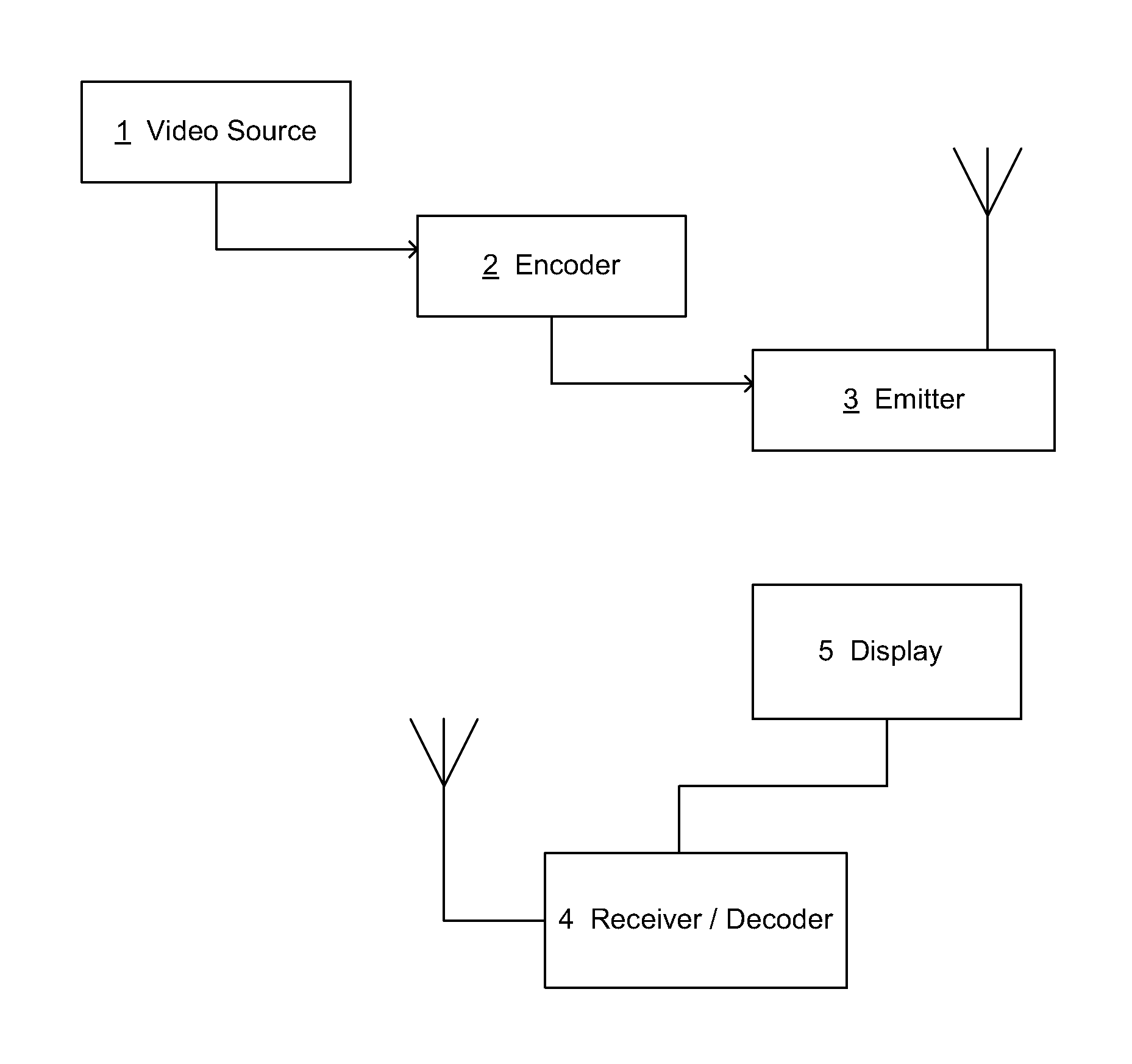
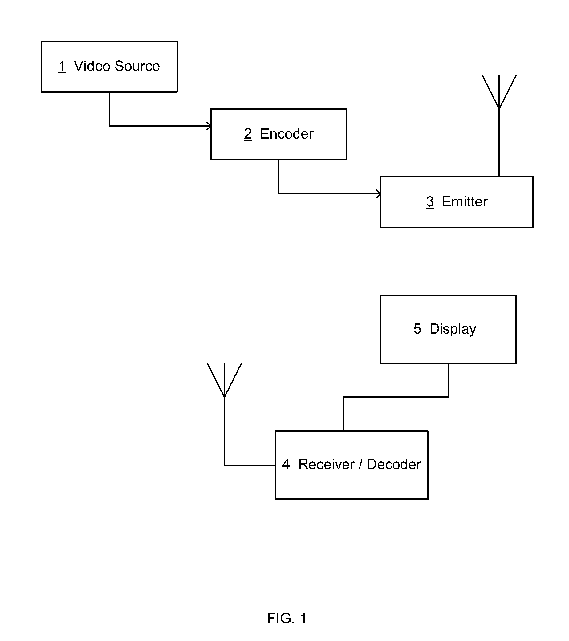
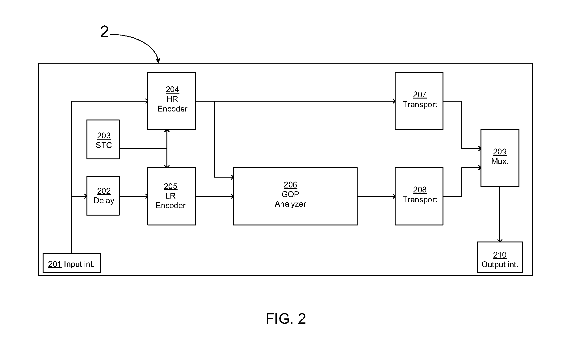
[0033]FIG. 1 describes a broadcast system according to a preferred embodiment of the invention. A video source 1 delivers a program to an encoder 2. The encoder encodes a first program in a full resolution according to the MPEG-2 compression standard and a second program in a lower resolution. According to the embodiment, the encoder includes a GOP analyzer module that compares PTS information associated with I picture of e...


PUM


Abstract

The present invention concerns a method for reducing the channel change time in a broadcast television system by encoding a termed companion service in addition to the main service. The companion service is sent along with the original service and helps the receiver to retrieve and display the new service more rapidly during the channel change process. With this solution the service is encoded and streamed in its original format, plus encoded and streamed in a low resolution format.

Description

FIELD OF THE INVENTION[0001]The present invention relates generally to a method for channel change time optimization and more particularly to a method to reduce the time to display a new selected program with bandwidth optimization.BACKGROUND OF THE INVENTION[0002]This section is intended to introduce the reader to various aspects of art, which may be related to various aspects of the present invention that are described and / or claimed below. This discussion is believed to be helpful in providing the reader with background information to facilitate a better understanding of the various aspects of the present invention. Accordingly, it should be understood that these statements are to be read in this light, and not as admissions of prior art.[0003]Many innovations have improved the television experience over the past few years, as for example the number of programs, the digital treatment, the definition of the pictures and the way to broadcast programs to the users over some new type...

Claims


Application Information

Patent Timeline
IPC IPC(8): H04N7/26
CPCH04N21/4307H04N21/242H04N21/23439H04N21/44016H04N5/50H04N21/234363H04N21/2365H04N21/4384H04N21/43072H04N7/12
Inventor GAUTIER, ERICLAURENT, ANTHONYTOUZE, DAVID
Owner INTERDIGITAL VC HLDG INC
Learn More