
Apparatus and method for protection switching of multiple protection group

a protection group and apparatus technology, applied in data switching networks, frequency-division multiplexes, instruments, etc., can solve the problem that conventional protection switching consumes a long time for protection switching to a protection

Inactive Publication Date: 2012-06-28
ELECTRONICS & TELECOMM RES INST
View PDF3 Cites 23 Cited by
  • Summary
  • Abstract
  • Description
  • Claims
  • Application Information

AI Technical Summary

Benefits of technology

[0009]The following description relates to a technique of quickly performing, when failure has occurred on a path belonging to a protection group in a packet transport network, protection switching to a protection path.
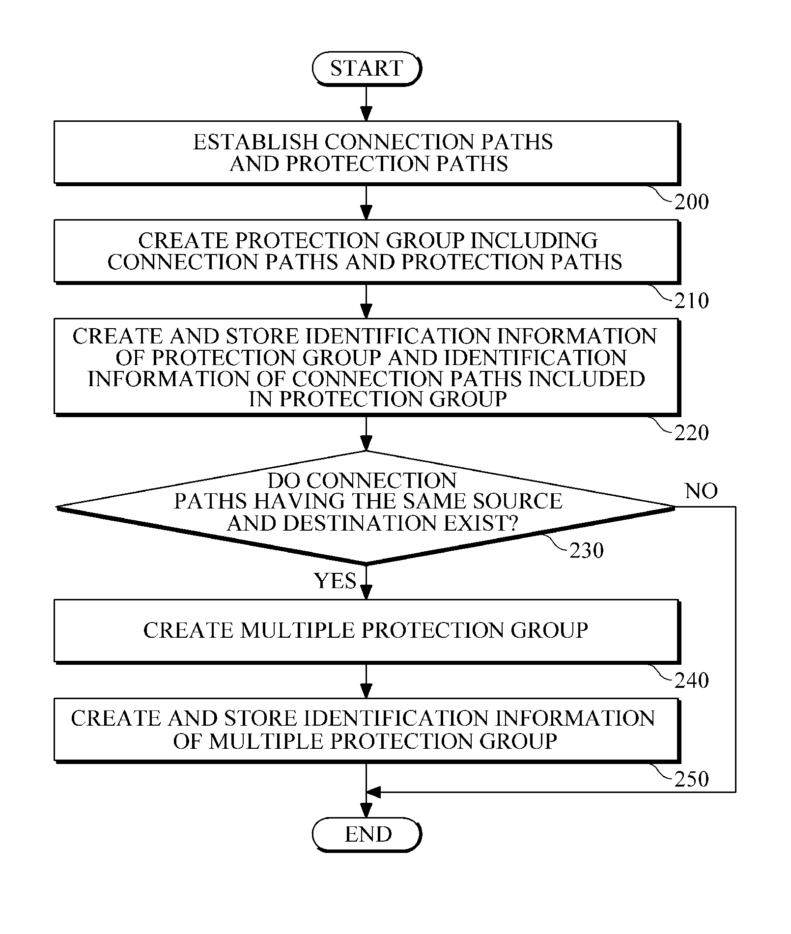
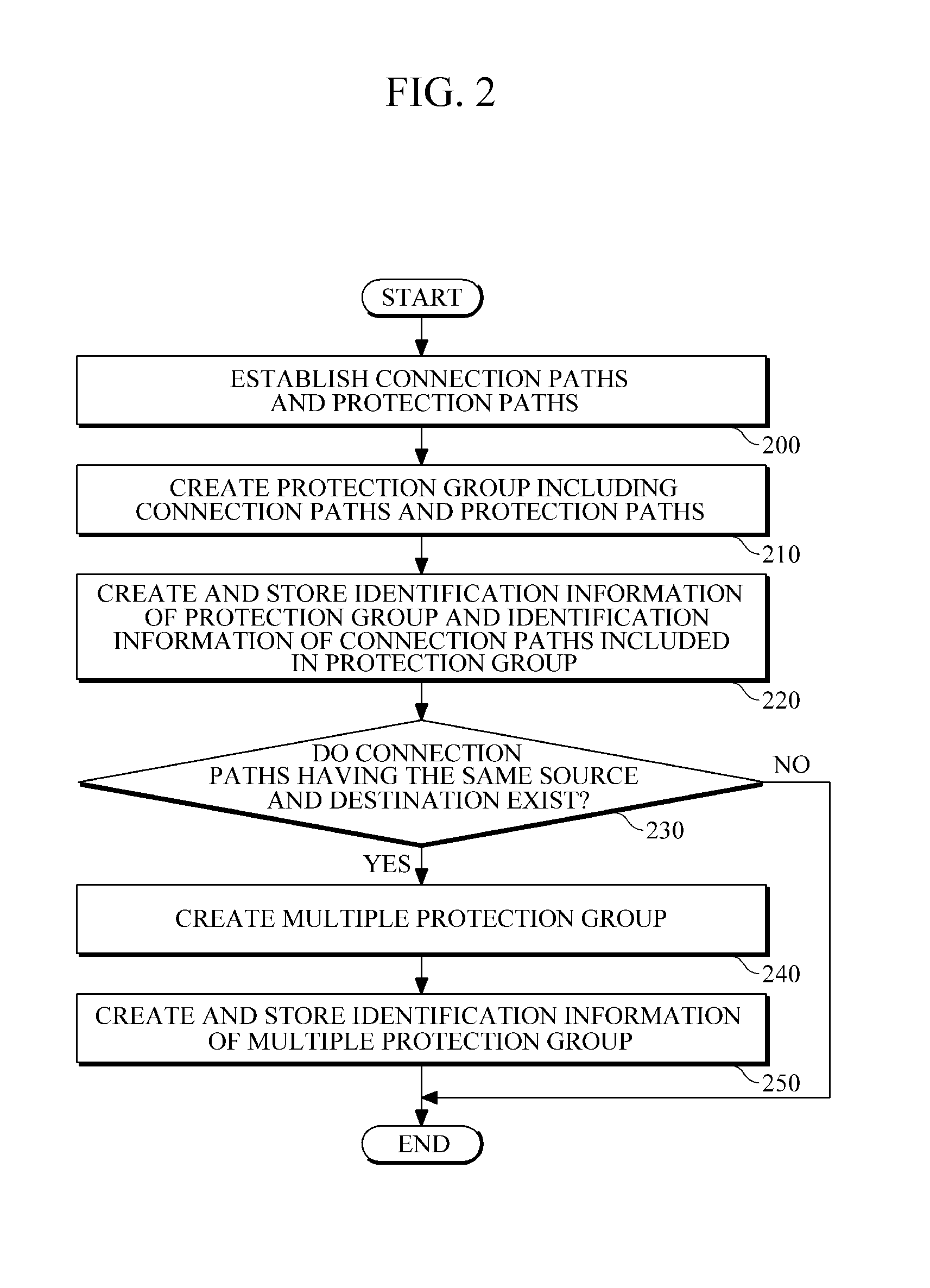
[0021]In the case where a plurality of paths for transmitting / receiving packets are established in a packet transport network, and some of the paths have the same source and destination, when failure has occurred on one of the paths having the same source and destination, the paths having the same source and destination are all protection switched to protection paths that can substitute for the corresponding paths, thereby reducing a time consumed for protection switching.

Problems solved by technology

However, in conventional protection switching, when a plurality of protection groups exist in a single management point, the protection groups individually manage the state and switching of connection paths, and accordingly a network device corresponding to the management point has to repeatedly perform protection switching several times. Accordingly, the conventional protection switching consumes a long time for protection switching to a protection path upon occurrence of failure on any connection path belonging to a protection group.

Method used


Image

  • Apparatus and method for protection switching of multiple protection group
  • Apparatus and method for protection switching of multiple protection group
  • Apparatus and method for protection switching of multiple protection group

Examples


Embodiment Construction

[0027]The following description is provided to assist the reader in gaining a comprehensive understanding of the methods, apparatuses, and / or systems described herein. Accordingly, various changes, modifications, and equivalents of the methods, apparatuses, and / or systems described herein will be suggested to those of ordinary skill in the art. Also, descriptions of well-known functions and constructions may be omitted for increased clarity and conciseness.

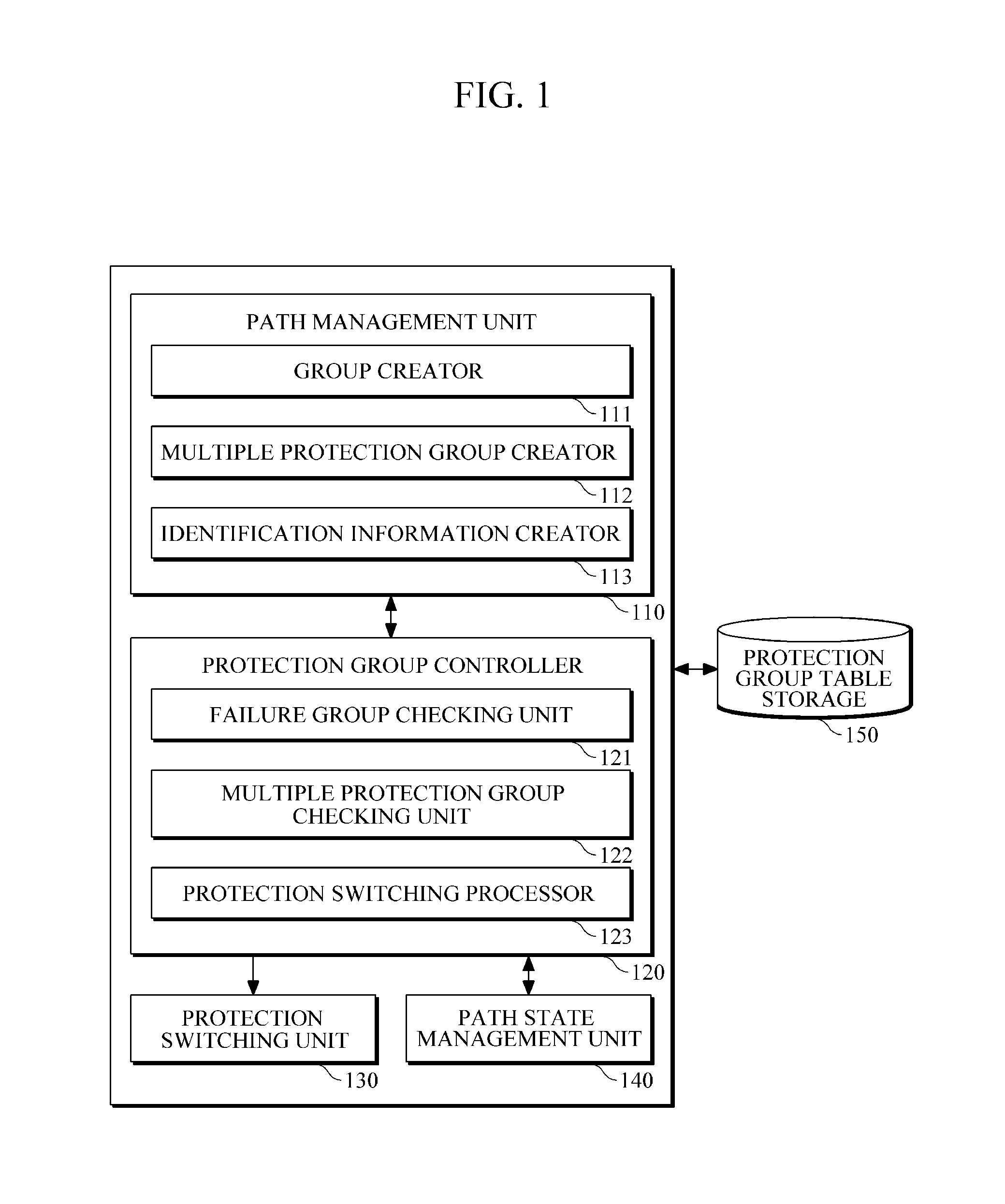
[0028]FIG. 1 is a diagram illustrating an example of a protection switching apparatus for protection switching of a multiple protection group.

[0029]Referring to FIG. 1, the protection switching apparatus includes a path management unit 110, a protection group controller 120, a protection switching unit 130, and a path state management unit 140.

[0030]The path management unit 110 establishes a plurality of connection paths for receiving and transmitting packets, and a plurality of protection paths that correspond to the connection p...


PUM


Abstract

There is provided a protection switching apparatus including: a path management unit to establish a plurality of connection paths for transmitting / receiving packets, and a plurality of protection paths that are able to substitute for the plurality of connection paths, respectively, and to create a protection group including the connection paths and the protection paths; a protection group controller to determine whether failure has occurred on the connection paths, based on path state information for each path included in the protection group, the path state information stored in the protection group table storage, and to issue an instruction for protection switching, according to the result of the determination; and a protection switching unit to perform protection switching of a path in which failure has occurred to a protection path corresponding to the path in which failure has occurred, according to the instruction for protection switching.

Description

CROSS-REFERENCE TO RELATED APPLICATION[0001]This application claims the benefit under 35 U.S.C. §119(a) of a Korean Patent Application No. 10-2010-0133822, filed on Dec. 23, 2010, the entire disclosure of which is incorporated herein by reference for all purposes.BACKGROUND[0002]1. Field[0003]The following description relates to a packet network or a packet transport network, and more particularly, to an apparatus and method for protection switching of a multiple protection group, in which when failure has occurred on a path for receiving and transmitting packets, quick protection switching to a protection path is performed.[0004]2. Description of the Related Art[0005]Along with increase of Internet users, traffic of communication networks is increasing exponentially, and users are requiring various services, such as high-speed data services, e-commerce, telemedicine, virtual education, real-time multimedia services, etc.[0006]Accordingly, in order to establish a stable communicatio...

Claims


Application Information

Patent Timeline
IPC IPC(8): H04L12/26H04L45/24H04L45/28
CPCH04L41/0663H04L41/0893H04L49/552H04L45/28H04L45/22H04L41/00H04L12/28
Inventor KIM, DAE-UBLEE, SANG-MINRYOO, JEONG-DONG
Owner ELECTRONICS & TELECOMM RES INST
Learn More