
Co2 sensing materials and sensors incorporating said materials

a technology of sensing materials and sensors, applied in the field of co2 sensing, can solve the problems of large operating power consumption, difficult operation, difficult to achieve, etc., and achieve the effect of increasing stability and additional protection

Inactive Publication Date: 2012-06-28
SILICON LAB INC
View PDF1 Cites 15 Cited by
  • Summary
  • Abstract
  • Description
  • Claims
  • Application Information

AI Technical Summary

Benefits of technology

[0029]In one embodiment, the gas-sensitive material is covered by a catalytically active oxide or precious metal material to provide increased stability and additional protection against nuisance gases.

Problems solved by technology

However, it is not a straightforward task, particularly in the case of CO2 measurement, which has often been performed by a non-dispersive infra-red (NDIR) technique.
This optical method can be quite accurate and selective, but devices tend to be large, expensive, and to consume large operating power.
A further restriction is that optical devices are unsuited for use in hot, hazardous conditions such as are encountered in combustion environments.
Slow response and recovery times, humidity interference, and high power consumptions have also been reported for these sensors.
Greater integration also generally results in lower power, due to reduced parasitic capacitances, important for battery-operated applications.
However broader success of MOS and other polymer materials as gas sensors in the marketplace has been limited due to a variety of reasons—performance issues related to material stability, baseline drift, and cross-sensitivity of the sensor material to other non-target gases and humidity.
Although SnO2 is the most widely deployed MOS material for gas-sensing, its problems with stability and humidity interference are well documented.
The sum total of all of these efforts is inadequate performance to meet the market requirement.
To date, commercial success in combustion environments has eluded MOS sensors.

Method used


Image

  • Co2 sensing materials and sensors incorporating said materials
  • Co2 sensing materials and sensors incorporating said materials
  • Co2 sensing materials and sensors incorporating said materials

Examples


example 1

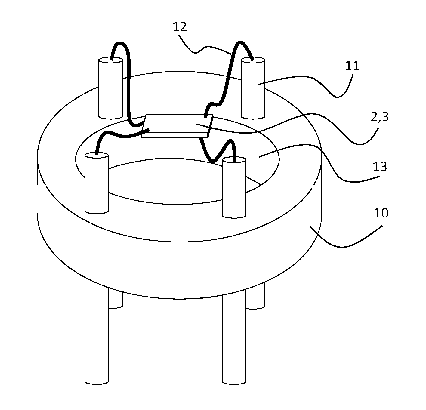
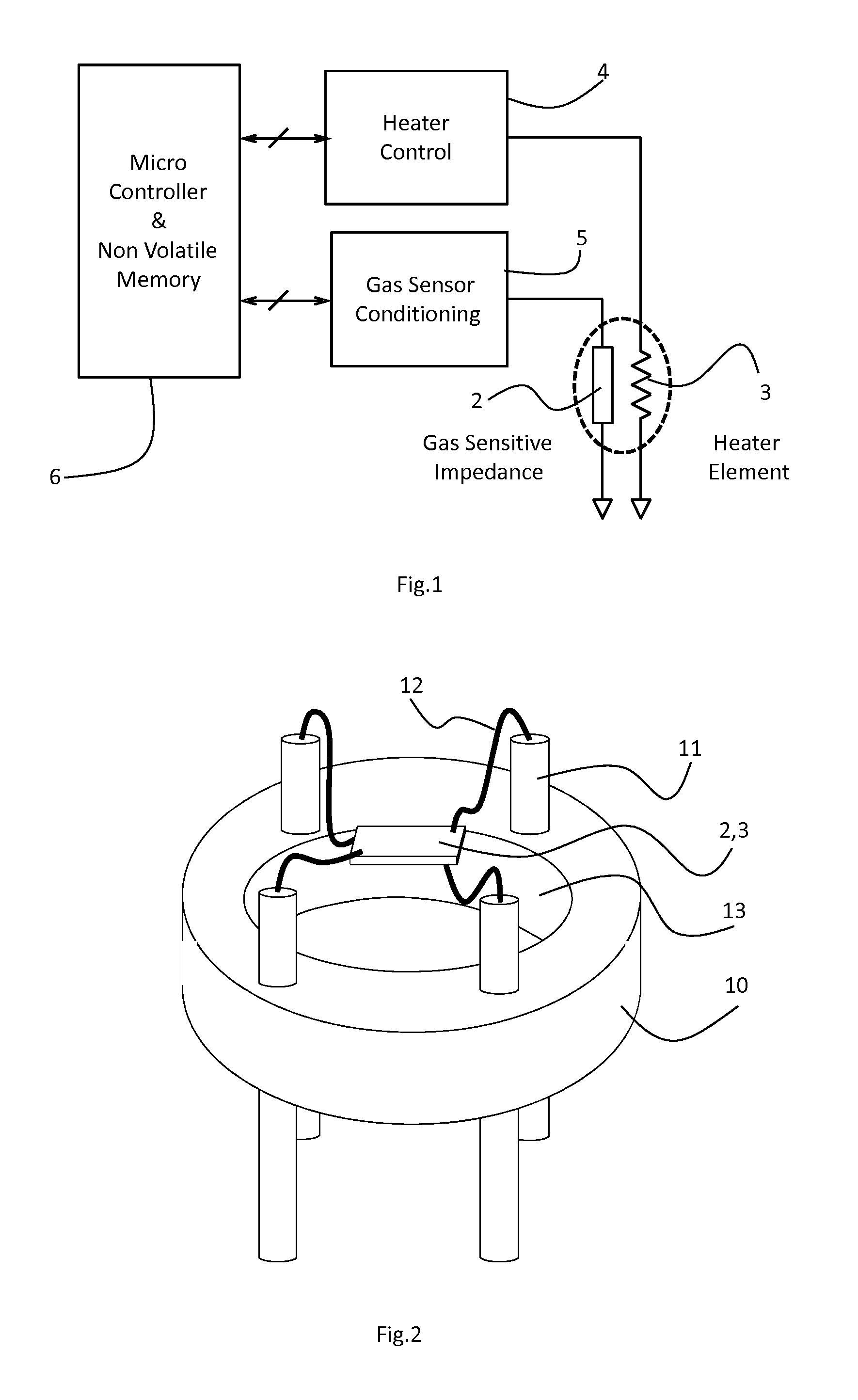
[0050]The gas-sensitive material was prepared by dry mixing commercial grade Barium Citrate powder (Aldrich, 325 mesh) with WO3 powder (New Metals, Ceramic Grade) in the ratio 66 mol %:33 mol % on a roller mill The powdered mixture was then heated to 750° C. for 1 hour, which resulted in a gas-sensitive material including the following crystalline phases as determined by X-ray diffraction: BaWO4 and WO3. The material was then converted into a screen-printable ink by mixing it with a commercial ink vehicle, ESL 400, in a ball mill, such that the solids loading was 85 wt %. The gas sensor was then fabricated using a 250 μm thick 2 m×2 m aluminium oxide chip with on one side a serpentine platinum heater track and on the other side an interdgitated gold electrode pattern (65 μm electrode digit spacing), upon which a 150 μm thick layer was screen-printed using a 1202 DEK printer. The sensor chip was mounted onto a 4-pinned base by means of welding platinum wires between the chip bond pad...

example 2

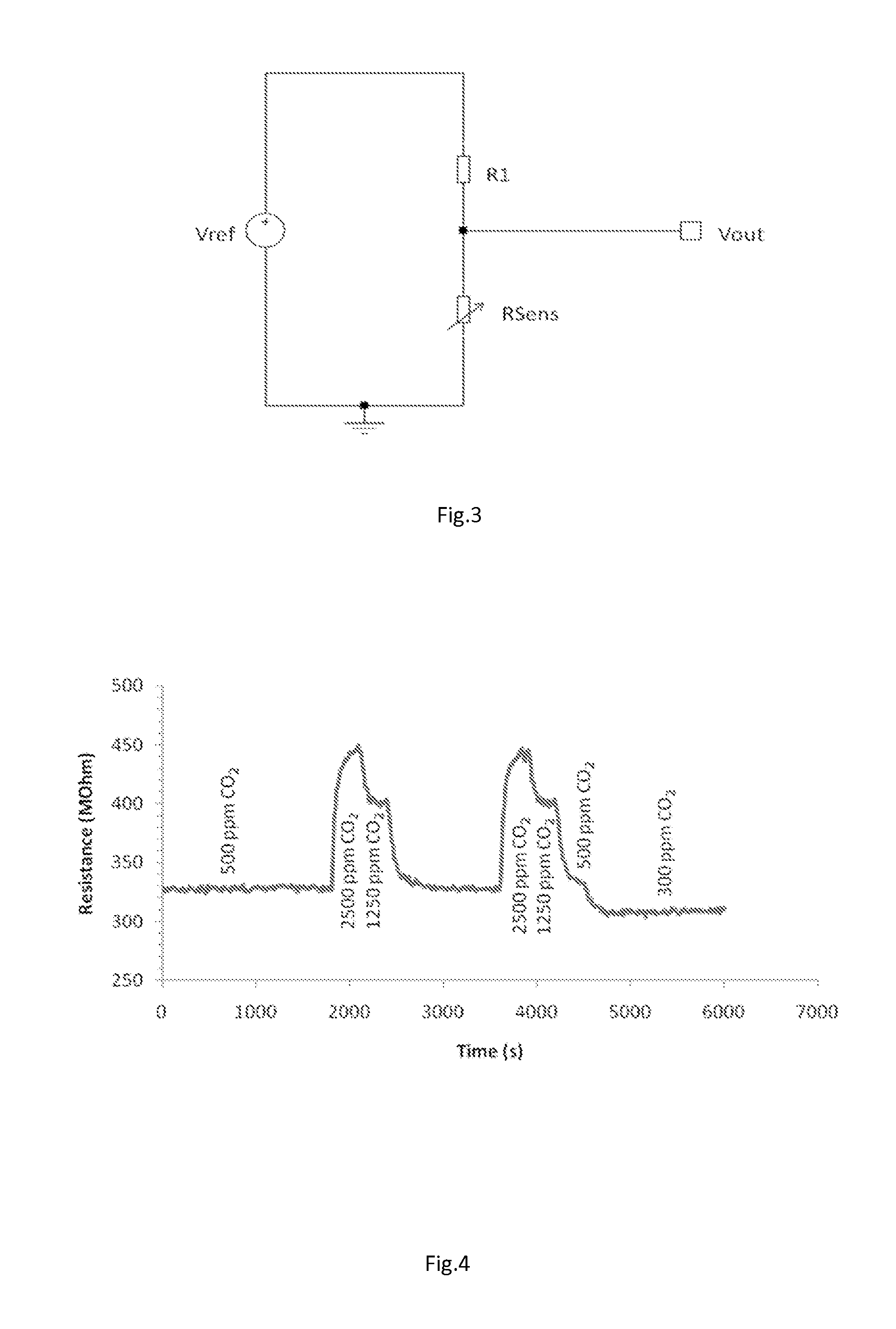
[0064]The gas-sensitive material was prepared by a wet chemistry route. A barium nitrate solution was prepared by dissolving 7.5 of BaNO3 in 100 ml of water. To this was added, 300 ml of methylene chloride while continuously stirring. To the resulting emulsion, a solution of tungsten tetrachloride (7.31 g dissolved in 150 ml of 6 molar potassium hydroxide solution) was added with constant stiffing and a gel was formed. The gel was thoroughly washed with water until no more white silver chloride was formed by the addition of AgNO3. The gel was dried at 50° C. overnight and subsequently fired at 800° C. for 4 hours. The calcined material was sieved through a 38 μm mesh and dispersed in an ESL 400 ink vehicle with a 80% solids loading to make a screen-printable ink. A sensor was fabricated along the same lines as in Example 1, and tested in CO2 gas using the following test program:[0065](i) 60 seconds in static air[0066](ii) 300 seconds in flowing 500 ppm CO2-balance air[0067](iii) 300...

example 3

[0072]A sensor chip as prepared as in Example 1 but in this case, two meter long Pt wires were connected to the sensor electrodes and the chip was placed on an aluminium oxide tile which itself was positioned on a sectioned ceramic furnace tube, as shown in FIG. 7. This sectioned tube was then placed in an outer tube in a furnace which allowed controlled atmospheres. The mounted sensor chip was ‘passively’ heated by the furnace atmosphere to 650° C. in an atmosphere comprising a background composition of (in volume %) N2, 10% O2, 3% H2O and 0.25% CO2. As shown in FIG. 8, the CO2 level was systematically increased in increments of 0.25% up to a maximum value of 4 vol % during the course of the test. Unlike in Example 1, the sensor was not conditioned by a firing to a higher temperature. It can be seen in FIG. 8 that the sensor responds to changes in CO2 in the range 1 to 3 vol % with a decrease in resistance. Below 1 vol %, the sensor may be equilibrating with its surroundings or is ...


PUM


Abstract

A gas-sensitive material is disclosed for detecting CO2 for use in semiconductor-based gas sensors. The gas-sensitive material may comprise one or more Ba-containing phases and one or more W-containing phases, at least one of the Ba-containing phases being different than at least one of the W-containing phases; the one or more Ba-containing phases comprising at least one of BaCO3, BaO-rich glass, BaWO4, or any combination thereof; and the one or more W-containing phases comprising at least one of BaWO4, WO3, W(OH)6, or any combination thereof. The material may further comprise one or more oxides selected from the group CuO, Bi2O3, Sb2O3, Sb2O5, La2O3, Cr2O3, Fe2O3, NiO, and TiO2, and any combination thereof. The material may further comprise one or more dopants such as Pt, Pd, Ag, Au or their compounds, and any combination thereof. In one embodiment, the material comprises a mixture of BaO-rich glass, BaWO4, and WO3. In another embodiment, the material comprises a mixture of at least one of BaCO3 or BaO-rich glass in combination with at least one of WO3 or W(OH)6. Transducers and sensors incorporating such gas-sensitive materials are also disclosed.

Description

FIELD OF THE INVENTION[0001]The disclosure herein relates to CO2 sensing, for example using metal oxide semiconducting technology.BACKGROUND OF THE INVENTION[0002]Accurate detection and measurement of gases is highly desirable for many reasons, including health and safety, environmental monitoring, and energy saving. However, it is not a straightforward task, particularly in the case of CO2 measurement, which has often been performed by a non-dispersive infra-red (NDIR) technique. This optical method can be quite accurate and selective, but devices tend to be large, expensive, and to consume large operating power. This is because of the large housing and gas chamber or tubing, infra-red beam generation, mirrors, reflectors, optical filters and detectors, together with hand-assembly.[0003]A further restriction is that optical devices are unsuited for use in hot, hazardous conditions such as are encountered in combustion environments. The current drive to make leaner engines and curta...

Claims


Application Information

Patent Timeline
IPC IPC(8): G01R27/08G01N25/00G01N33/00
CPCG01N27/125
Inventor SMITH, PETERCAVANAGH, LEON
Owner SILICON LAB INC
Learn More