Method and system for passive resonant voltage switching

a voltage switching and passive resonant technology, applied in the field of voltage switching systems, can solve the problems of reducing the fidelity of the system in characterizing different materials, not always providing the switching speed needed for certain imaging applications, and cardiac imaging cannot be effectively performed

Active Publication Date: 2012-06-21
GENERAL ELECTRIC CO
View PDF2 Cites 19 Cited by
  • Summary
  • Abstract
  • Description
  • Claims
  • Application Information

AI Technical Summary

Benefits of technology

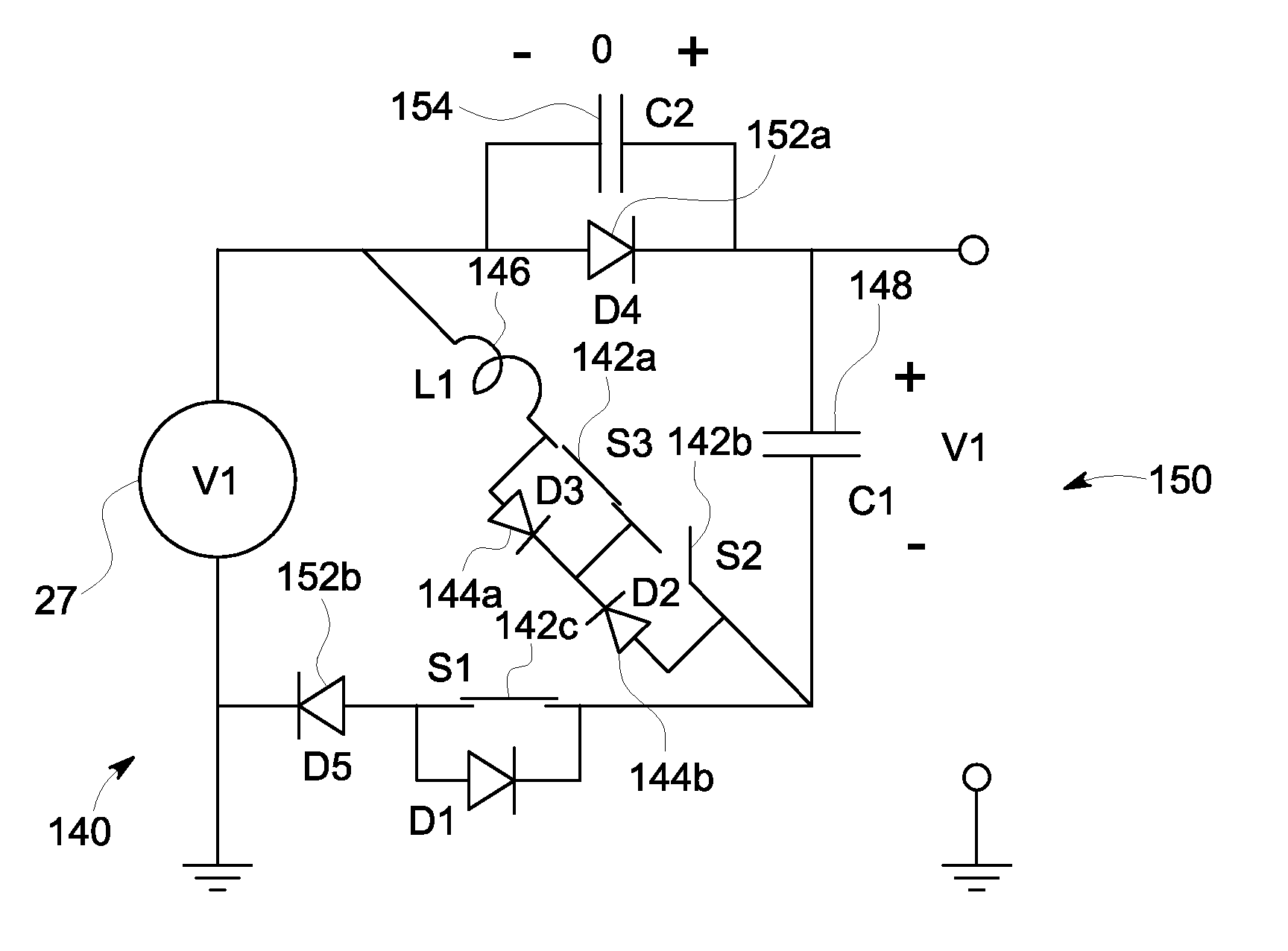
[0011]In accordance with other various embodiments, a high voltage generator system is provided that includes a voltage source and a passive resonant interposer circuit connected to the voltage source. The passive resonant interposer circuit includes a plurality of passive resonant switching modules configured to output two different voltage levels using resonant swit

Problems solved by technology

Less stable x-ray tube operating voltages and / or slower operating voltage switching times result in a reduction in the difference in effective mean energy (the average of the mean energies of time-varying x-ray spectra) of the applied x-ray spectra, which reduces the fidelity of the system in characterizing different materials.
Thus, while switching the x-ray tube potential (voltage), for example, by using high-frequency generators, may solve some of the problems related to conventional dual-energy scanning (acquiring energy-sensitive projection data on alternate scans of the object), such a configuration does not always provide the switching speed needed for certain imaging applications.
For example, cardiac imaging cannot be effectively performed by simply switching the x-ray source potential between two sequential scans of the human thorax due to cardiac motion.
Furthermore, for systems utilizing rapid switching of the x-ray potential for subsets of projection angles, the switching speed of the x-ray tube potential may not be sufficient for the fast gantry rotation speeds required to freeze motion for cardiac imaging.
There is often a delay in the response time of the switched operating potential between the high-frequency generator and the x-ray tube, due in part to the capacitance of the cable connecting the device and the x-ray tube.
Similarly, the fall time between switching the high kVp to a low kVp level is generally very slow due to the need to discharge the system capacitance, which effectively reduces the energy separation of the applied spectra, resulting in reduced material specification sensitivity and, therefore, the effectiveness of the dual-energy imaging.
As such, these insufficient switching speeds often lead to projection data pair mis-registration and streak artifacts in reconstructed images.
As such, the time required to switch the operating voltage of the x-ray tube is prohibitively long.
For radiographic x-ray imaging systems, the limitations mentioned above also apply.
The aforementioned limitations regarding switching speed apply to x-ray radiographic or tomosynthesis systems, such as due to the capacitance of the high-voltage cable connecting the generator to the x-ray tube, the x-ray tube capacitance itself, the power of the generator, and the x-ray beam current, which may all limit switching speed.

Method used


Image

  • Method and system for passive resonant voltage switching
  • Method and system for passive resonant voltage switching
  • Method and system for passive resonant voltage switching

Examples


Embodiment Construction

[0029]The foregoing summary, as well as the following detailed description of certain embodiments will be better understood when read in conjunction with the appended drawings. As used herein, an element or step recited in the singular and proceeded with the word “a” or “an” should be understood as not excluding plural of said elements or steps, unless such exclusion is explicitly stated. Furthermore, references to “one embodiment” are not intended to be interpreted as excluding the existence of additional embodiments that also incorporate the recited features. Moreover, unless explicitly stated to the contrary, embodiments “comprising” or “having” an element or a plurality of elements having a particular property may include additional elements not having that property.

[0030]The various embodiments are described herein within a particular operating environment including a particular imaging system, such as a “third generationcomputed tomography (CT) system (e.g., a sixty-four-sli...


PUM


Abstract

Methods and systems for passive resonant voltage switching are provided. One passive resonant switching system includes a voltage switching system having one or more passive resonant modules to provide a switching voltage output. Each of the passive resonant modules include switching devices configured to operate in open and closed states to produce first and second voltage level outputs from a voltage input. The passive resonant modules also include a capacitor connected to the one or more switching devices and configured to receive a system discharge energy during a resonant operating cycle when switching an output voltage from the first voltage level to the second voltage level, and to be recharged when switching from the second to first voltage level. The passive resonant modules further include a resonant inductor and an additional switching device.

Description

BACKGROUND OF THE INVENTION[0001]The subject matter disclosed herein relates generally to voltage switching systems, and more particularly, to methods and apparatus for voltage switching in imaging systems, such as diagnostic x-ray imaging systems.[0002]In conventional computed tomography (CT) x-ray imaging systems, an x-ray source emits a cone-shaped beam of x-rays toward a subject or object, such as a patient. The beam, after being attenuated by the subject, impinges upon an array of radiation detectors. The intensity of the attenuated beam radiation received at the detector array is dependent upon the attenuation of the x-ray beam by the subject. Each detector element of the detector array produces a separate electrical signal indicative of the x-ray intensity received by that detector element. The electrical signals are quantized and transmitted to a data processing system for analysis, which ultimately produces an image.[0003]CT imaging systems may comprise energy-discriminatin...

Claims


Application Information

Patent Timeline
IPC IPC(8): H05G1/32H03K3/00
CPCH05G1/10H03K3/53
Inventor CAIAFA, ANTONIOEDIC, PETER MICHAELWILSON, COLIN RICHARD
Owner GENERAL ELECTRIC CO
Why Eureka
Try Eureka