Power amplifying apparatus

Active Publication Date: 2012-06-21
SAMSUNG ELECTRO MECHANICS CO LTD
View PDF6 Cites 0 Cited by
  • Summary
  • Abstract
  • Description
  • Claims
  • Application Information

AI Technical Summary

Benefits of technology

[0016]An aspect of the present invention provides a power amplifying apparatus having a reduction in size and manufacturing costs by being configured without a current mirror circuit and having improved current control performance by removing a load limiting phenomenon.

Problems solved by technology

However, the power amplifying apparatus according to the related art includes the current mirror circuit, thereby causing increases in both the size and cost thereof.
In addition, since the power amplifying apparatus includes the current mirror circuit, as an electrical length of a passive element included in the power amplifying apparatus becomes elongated, an error is generated between the sensed voltage and the reference voltage, such that the driving current may not be accurately controlled.

Method used


Image

  • Power amplifying apparatus
  • Power amplifying apparatus
  • Power amplifying apparatus

Examples


Embodiment Construction

[0030]Exemplary embodiments of the present invention will now be described in detail with reference to the accompanying drawings.

[0031]The present invention should not be limited to the embodiments set forth herein and the embodiments may be used to assist in understanding the technical idea of the present invention. Like reference numerals designate like components having substantially the same constitution and function in the drawings of the present invention.

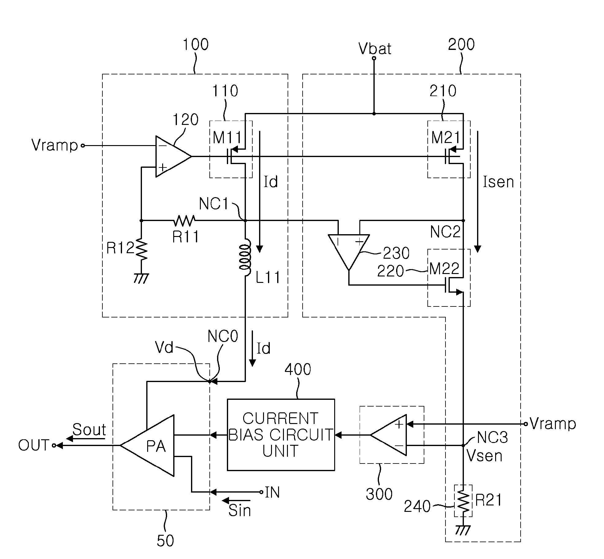
[0032]FIG. 1 is a block diagram of a power amplifying apparatus according to an exemplary embodiment of the present invention.

[0033]Referring to FIG. 1, a power amplifying apparatus according to an exemplary embodiment of the present invention includes a power amplifier 50 amplifying an input signal Sin provided through an input terminal IN to output an output signal Sout through an output terminal OUT.

[0034]The power amplifying apparatus may include a power regulator 100 receiving a power supply voltage Vbat through a first ...


PUM


Abstract

There is provided a power amplifying apparatus including: a power amplifier; a power regulator providing a driving voltage and a driving current corresponding to a control voltage to the power amplifier; a current sensing unit sensing a current and a voltage corresponding to the driving current and controlling the driving voltage according to the sensed current; a current control unit controlling a current bias according to the sensed voltage of the current sensing unit; and a current bias circuit unit controlling a bias current of the power amplifier according to the controlling of the current control unit.

Description

CROSS-REFERENCE TO RELATED APPLICATIONS[0001]This application claims the priority of Korean Patent Application No. 10-2010-0128302 filed on Dec. 15, 2010, in the Korean Intellectual Property Office, the disclosure of which is incorporated herein by reference.BACKGROUND OF THE INVENTION[0002]1. Field of the Invention[0003]The present invention relates to a power amplifying apparatus, and more particularly, to a power amplifying apparatus applicable to a communication device transmission system and having improved current control performance and a reduction in size and cost as compared to the related art without the need for a separate current mirror circuit for sensing current.[0004]2. Description of the Related Art[0005]Generally, in a radio frequency (RF) block of a mobile communications terminal, a power amplifier is used in order to amplify an RF signal output.[0006]Research into a power amplifier, to which complementary metal oxide semiconductor (CMOS) technology appropriate for...

Claims


Application Information

Patent Timeline
IPC IPC(8): H03F3/21H03F1/22
CPCH03F1/0261H03F3/195H03F2200/78H03F2200/462H03F2200/471H03F3/24
Inventor NA, JUN KYUNGKIM, YOUN SUKHA, SANG HOONIIZUKA, SHINICHIPARK, SANG WOOK
Owner SAMSUNG ELECTRO MECHANICS CO LTD
Why Eureka
Try Eureka