
Computerized Planning Tool For Spine Surgery and Method and Device for Creating a Customized Guide for Implantations

a technology of spine surgery and planning tool, which is applied in the direction of instruments, prostheses, applications, etc., can solve the problems of not knowing exactly where each screw will go, how much distraction will be applied, or what length of screw or rod will be needed, and it is difficult for surgeons to predict preoperative images. to achieve the effect of maximizing the accuracy of prediction, ensuring correct alignment of implants, and reducing labor

Inactive Publication Date: 2012-06-14
DIGNITY HEALTH
View PDF7 Cites 91 Cited by
  • Summary
  • Abstract
  • Description
  • Claims
  • Application Information

AI Technical Summary

Benefits of technology

The present invention is a computerized tool for planning surgery that uses a haptic interface and a computer to simulate a surgical procedure and provide feedback to the surgeon. The tool can also include a rapid prototyping unit to create models of the anatomical region where the surgical procedure will be performed or an alignment device to be used during the actual surgical procedure. The tool can also suggest improvements to the surgeon's plan. Overall, the invention helps improve the accuracy and efficiency of surgery planning and reduces the risk of complications.

Problems solved by technology

The surgical plan that is created based on these images is typically only a rough outline of the actual surgical procedure, as the surgeon is generally unable to accurately predict the reaction of the patient's anatomy in response to the introduction of surgical tools into the body.
For example, a surgeon may decide that a surgical procedure calls for a two-level pedicle screw-rod fixation to be performed, but he will not know prior to surgery exactly where each screw will go, how much distraction will be applied, or what length of screw or rod will be needed.
In some cases of extreme degeneration or severe injury, the anatomy of the spine may be grotesquely distorted.
In these cases, it becomes especially difficult for the surgeon to predict from the preoperative images what he or she can expect to encounter once resections are made and bony structures are realigned.
Several methods have been discussed that attempt to overcome the problems with spine surgery, but none of these methods is an adequate solution.
However, the usage of three-dimensional models alone has been found to be an inadequate planning tool.
Because the models are rigid and have homogenous material properties, the surgeon can practice only limited aspects of surgery with them, such as placing screws or pre-bending plates.
An articulated realistic physical model, which responds to drilling and cutting similarly to the actual patient's spine, although more desirable than a rigid model, is likely infeasible since such a model would entail an exorbitant amount of preoperative engineering and fabrication work for each patient.
However, although a three-dimensional image of the spine can be manipulated with CAD software; such manipulation does not simulate the surgery realistically.
Using a mouse to put surgical instrument into place on a CAD model does not accurately reflect the real surgical procedure and therefore does not provide the surgeon with a realistic experience.
Further, potentialities for surgical errors may be missed as a result of not having tactile feedback; if a surgeon accidentally tries to drill a screw hole in a trajectory that inadvertently crosses the pedicle wall and violates the spinal canal, such a mistake may go unnoticed if a mouse is used to place the screw, but in an actual procedure this mistake would be evidenced by the sensation of suddenly easier penetration of the drill.
Further, once the surgery is commenced, a common problem with artificial intervertebral discs in the cervical, thoracic, or lumbar spine is placement of the device off-center or improperly angled in the disc space.
Such improper alignment can theoretically lead to incorrect loading and kinematics of that motion segment, possibly causing pathological response such as pain, facet fusion, bony bridging of the device, or facet hypertrophy.
However, even after following the correct procedure outlined by the manufacturer, alignment may be off because of asymmetry in the anatomy, difficulty in aligning and interpreting radiographic images, incomplete resection of surrounding soft tissues obscuring full view, or change in path after initial insertion but before final seating of the device.
Other spinal implants have similar problems in alignment.

Method used


Image

  • Computerized Planning Tool For Spine Surgery and Method and Device for Creating a Customized Guide for Implantations
  • Computerized Planning Tool For Spine Surgery and Method and Device for Creating a Customized Guide for Implantations
  • Computerized Planning Tool For Spine Surgery and Method and Device for Creating a Customized Guide for Implantations

Examples


Embodiment Construction

[0022]While the present invention is susceptible of embodiment in various forms, there is shown in the drawings and will hereinafter be described a presently preferred embodiment with the understanding that the present disclosure is to be considered an exemplification of the invention and is not intended to limit the invention to the specific embodiment illustrated. It should be further understood that the title of this section of this specification, namely, “Detailed Description of the Invention”, relates to a requirement of the United States Patent Office, and does not imply, nor should be inferred to limit the subject matter disclosed herein.

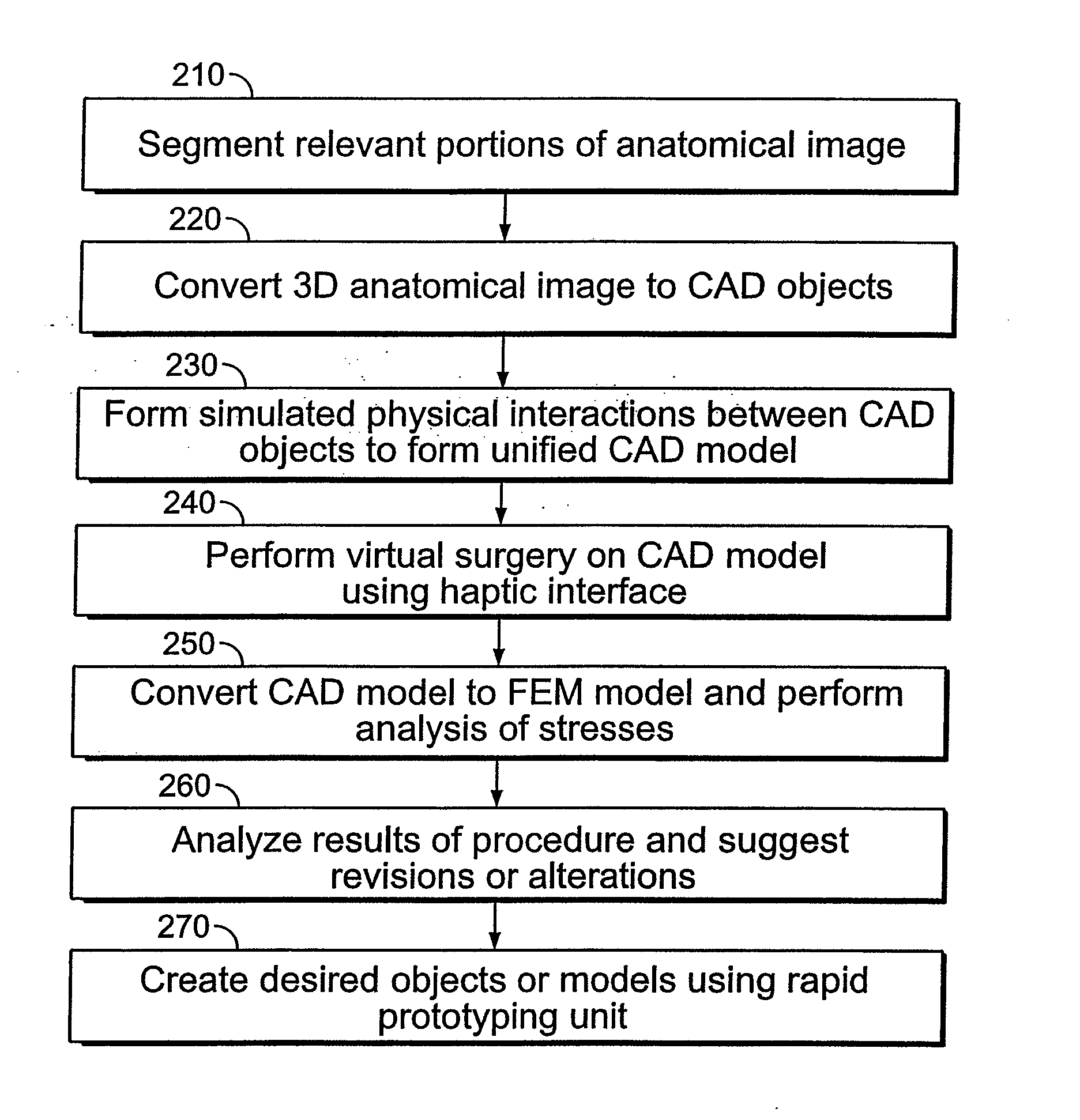
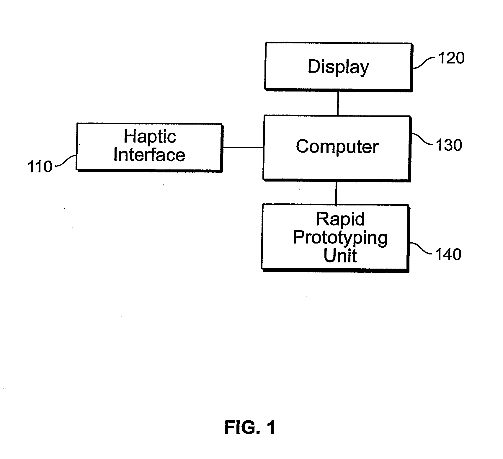
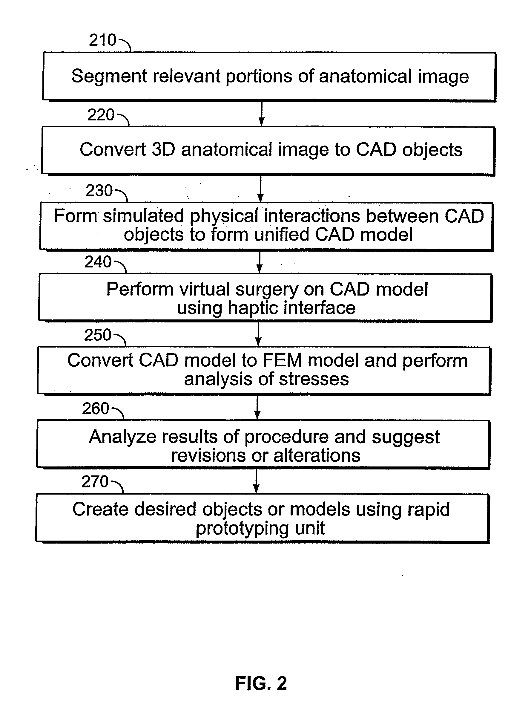
[0023]Referring now to FIG. 1, a system diagram of the computerized planning tool for spine surgery according to one embodiment of the invention is shown. FIG. 1 includes a haptic interface 110 that allows the user to interface with computer 130. The simulated surgery is displayed to the user on display 120. Computer 130 is also in communicat...


PUM


Abstract

A system for planning a spine surgery, comprising a haptic interface capable of providing force feedback to the user and a computer adapted to simulate a surgical procedure by responding to inputs from the haptic interface and outputting haptic feedback to the haptic interface is provided.The system further comprising a rapid prototyping unit including a unit that is adapted to create models of the anatomical region where the surgical procedure will be performed in its current unoperated condition and in the predicted postoperative condition. Further the rapid prototyping unit is adapted to create a three dimensional guide to be used in the surgical procedure as well as suggest revisions to the surgical procedure. The system further comprises a computer that simulates loading of the spine and planned implanted hardware using finite element software.

Description

CROSS-REFERENCE TO RELATED APPLICATIONS[0001]This invention claims priority to U.S. Provisional Patent Application No. 60 / 841,469, titled “A Computerized Planning Tool for Spine Surgery”, filed Aug. 31, 2006 and U.S. Provisional Patent Application No. 60 / 828,039 filed Oct. 3, 2006, titled “Customized Artificial Disc Alignment Guide”. The contents of these applications are incorporated by reference into this application as if fully set forth herein.FIELD OF THE INVENTION[0002]This invention generally relates to computerized tool for planning spinal surgery, and, more particularly, for a computerized tool with which a surgeon can perform a simulated surgery using a haptic interface to get an accurate prediction of how to proceed during the actual surgery, suggesting revisions, and creating a three-dimensional model based on the planned procedure. Further, the invention includes the accumulation of data such that the surgeon can, upon completion of the simulated surgery, order a custom...

Claims


Application Information

Patent Timeline
Patent Type & Authority Applications(United States)
IPC IPC(8): A61B17/56G06F17/50G06G7/48G06F19/00
CPCA61B2019/502A61F2/4425G06F19/3481G06F19/3437A61F2/4455A61B2034/102G16H50/50B33Y80/00G16H20/40
Inventor CRAWFORD, NEIL R.THEODORE, NICHOLASBAEK, SEUNGWONSAWA, ANNA G.U.
Owner DIGNITY HEALTH
Learn More