
Gate drive circuit and display apparatus having the same

a technology of gate drive circuit and display apparatus, which is applied in the direction of pulse generator, pulse technique, instruments, etc., can solve the problems of high temperature noise in the gate signal, visible noise defects such as ripples, and achieve the effects of reducing power consumption, enhancing driving reliability and reducing the integrated area of the gate drive circui

Active Publication Date: 2012-06-07
SAMSUNG DISPLAY CO LTD
View PDF2 Cites 87 Cited by
  • Summary
  • Abstract
  • Description
  • Claims
  • Application Information

AI Technical Summary

Benefits of technology

[0010]Exemplary embodiments of the present invention provide a amorphous silicon gate (“ASG”) type gate drive circuit capable of enhancing a driving reliability thereof and capable of decreasing the integrated circuit area thereof.
[0034]In an exemplary embodiment, the discharging part includes first discharging switch, a sub-discharging resistance and a second discharging switch. The first discharging switch discharges a high voltage of the first node to the second low voltage in response to the (n+1)th carry signal. The second discharging switch discharges a high voltage of the first node to the second low voltage in response to the (n+2)th carry signal. The sub-discharging resistance slows the discharge of the high voltage of the first node to the second low voltage.
[0037]According to some exemplary embodiments of the present invention, a voltage between the control gate and the output electrode of the first transistor in the pull-up part has a negative voltage after gate signals are outputted, so that conventionally added transistors for controlling noise may be omitted. Thus, the integrated area of the gate drive circuit may be decreased. Moreover, power consumption may be decreased. Furthermore, the voltage at the carry node is stably maintained at a low voltage, so that the driving reliability of the gate drive circuit may be enhanced.

Problems solved by technology

When the gate driving circuit integrated in the integrated circuit formed on the display substrate is driven in high temperature conditions, visible noise defects such as ripples may be generated during a “gate-OFF signal” period.
When the temperature of the gate drive circuit is increased due to a long operating time, a high temperature noise is generated in the gate signal.

Method used


Image

  • Gate drive circuit and display apparatus having the same
  • Gate drive circuit and display apparatus having the same
  • Gate drive circuit and display apparatus having the same

Examples


Embodiment Construction

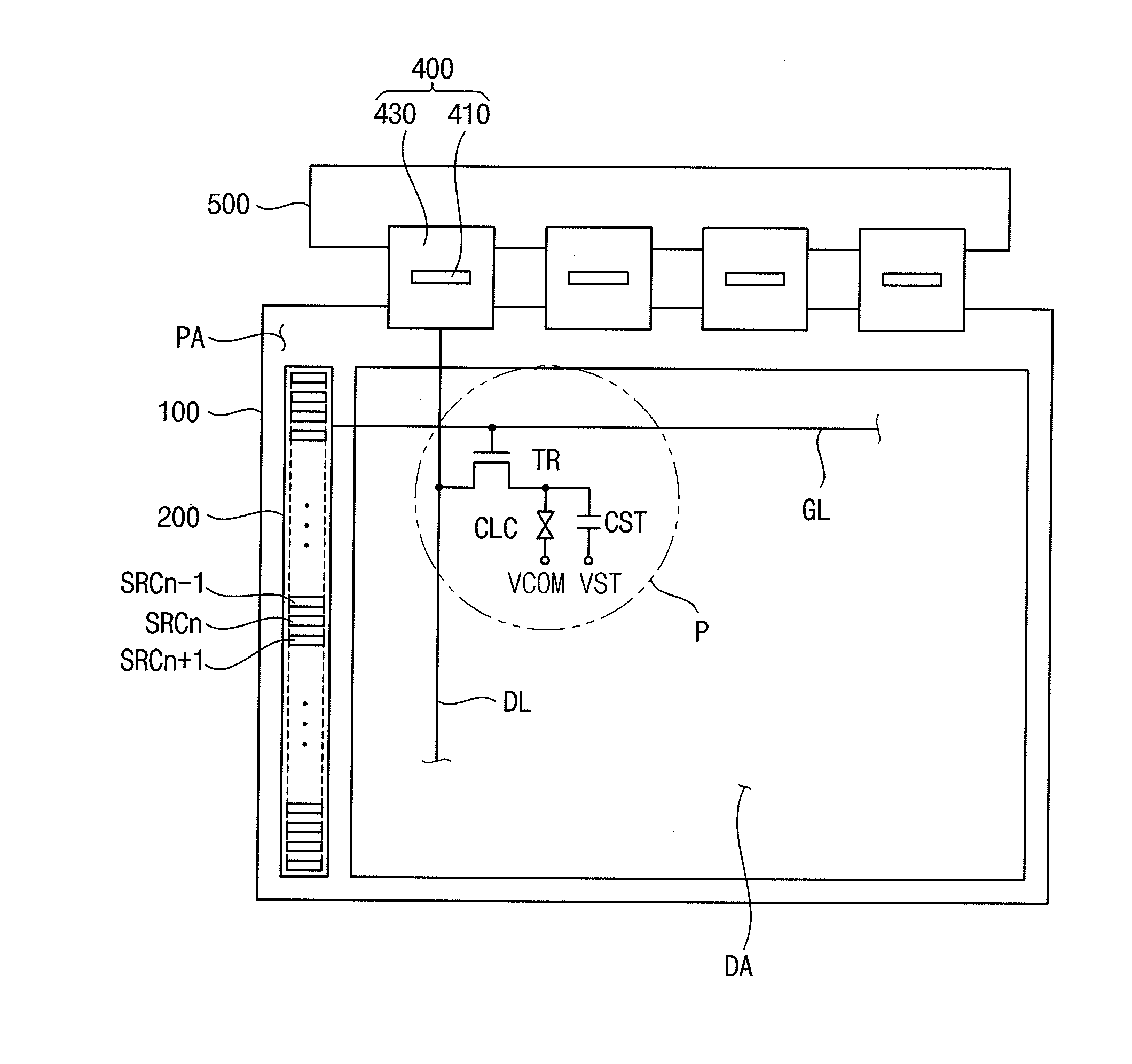
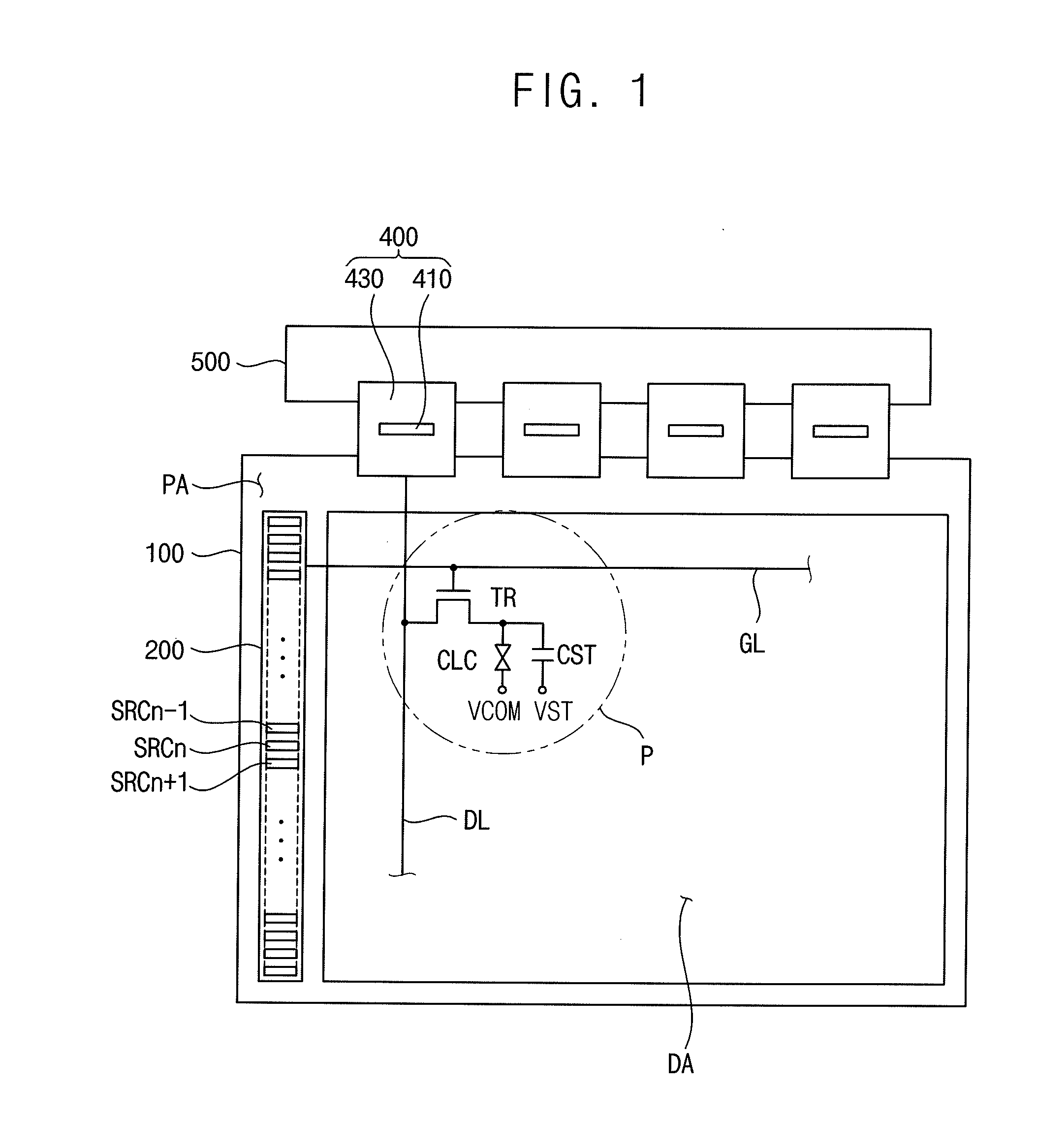
[0065]FIG. 1 is a schematic plan view of a display apparatus comprising a gate drive circuit including stages SRCn according to an exemplary embodiment of the present invention.

[0066]Referring to FIG. 1, the display apparatus includes a display panel 100, a gate drive circuit 200, a source drive circuit 400 and a printed circuit board (“PCB”) 500.

[0067]The display panel 100 includes a display area DA and a peripheral area PA surrounding the display area DA. A plurality of gate lines GL, a plurality of source lines DL and a plurality of pixels P are formed on the display area DA. The gate lines and the source lines cross each other. Each of the pixels P includes a switching element (transistor) TR electrically having its control gate connected to the gate line GL of that pixel P. The switching element (transistor) TR is connected between the source line DL and a liquid crystal capacitor CLC electrically connected to the switching element TR, and a storage capacitor CST connected in p...


PUM


Abstract

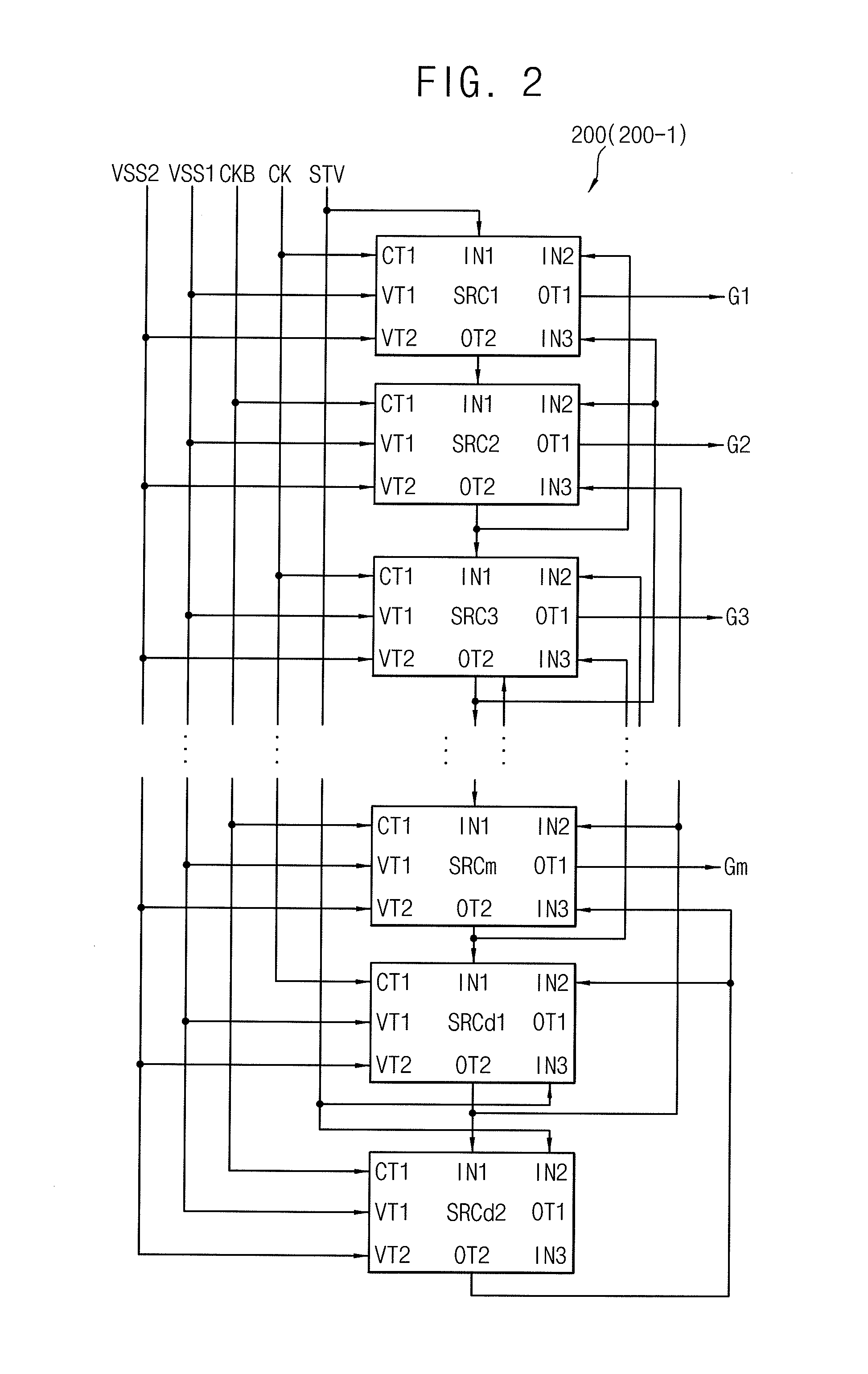
A gate drive circuit includes a shift register in which plural stages are cascade-connected to each other. In an n-th stage, a pull-up part outputs a high voltage of a clock signal to an output node as a high voltage of an n-th gate signal in response to a high voltage on a first node. A pull-down part pulls the high voltage of the n-th gate signal down to a first low voltage in response to an (n+1)th carry signal. A discharging part discharges the first node to a second low voltage level lower than the first low voltage level in response to the (n+1)th carry signal. A carry part outputs the high voltage of the clock signal as an n-th carry signal (mirroring the n-th gate signal) in response to a high voltage on the first node.

Description

PRIORITY STATEMENT[0001]This application claims priority, under 35 U.S.C. §119, of Korean Patent Application No. 2010-121728, filed on Dec. 2, 2010 and Korean Patent Application No. 2011-0073560, filed on Jul. 25, 2011 in the Korean Intellectual Property Office (KIPO), the contents of which are herein incorporated by reference in their entireties.BACKGROUND OF THE INVENTION[0002]1. Field of the Invention[0003]Exemplary embodiments of the present invention relate to a gate drive circuit and a display apparatus having the gate drive circuit. More particularly, exemplary embodiments of the present invention relate to a gate drive circuit, an integrated area of which is decreased and a display apparatus having the gate drive circuit.[0004]2. Description of the Related Art[0005]Generally, a liquid crystal display (“LCD”) device includes an LCD panel that displays images using a light-transmitting ratio of liquid crystal molecules, and a backlight assembly disposed below the LCD panel to ...

Claims


Application Information

Patent Timeline
IPC IPC(8): G06F3/038H03K3/00
CPCG09G3/3611G09G3/3677G09G2310/0286G09G2300/0408G09G2320/041G11C19/28
Inventor LEE, JAE-HOONKIM, YOUNG-SULEE, WHEE-WONSONG, JUN-YONGBAE, YU-HANHYUN, YOU-MEE
Owner SAMSUNG DISPLAY CO LTD
Learn More