
Electromagnetic array for subterranean magnetic ranging operations

a technology of electromagnetic array and subterranean borehole, which is applied in the direction of magnetic measurement, instruments, constructions, etc., can solve the problems of difficulty in computing the relative position of the drilling well, and achieve the effects of improving the accuracy of subterranean magnetic ranging operations, improving the placement of wells, and improving accuracy

Inactive Publication Date: 2012-06-07
SCHLUMBERGER TECH CORP
View PDF11 Cites 40 Cited by
  • Summary
  • Abstract
  • Description
  • Claims
  • Application Information

AI Technical Summary

Benefits of technology

[0007]Exemplary embodiments of the present invention provide several potential advantages. In particular, the invention tends to improve the accuracy of subterranean magnetic ranging operations. Such improved accuracy tends to result in improved well placement in various intercept and twinning operations. The invention further provides multiple independent ranging methodologies for determining the relative position between the wellbores. These multiple methods tend to provide redundancy and increased operational flexibility in a wide variety of ranging operations. These and other advantages of the invention are discussed in more detail below.

Problems solved by technology

For example, difficulties remain in computing an accurate relative position of the drilling well with respect to the target well (i.e., between the magnetic field sensor in the drilling well and the electromagnetic source in the target well).

Method used


Image

  • Electromagnetic array for subterranean magnetic ranging operations
  • Electromagnetic array for subterranean magnetic ranging operations
  • Electromagnetic array for subterranean magnetic ranging operations

Examples


Embodiment Construction

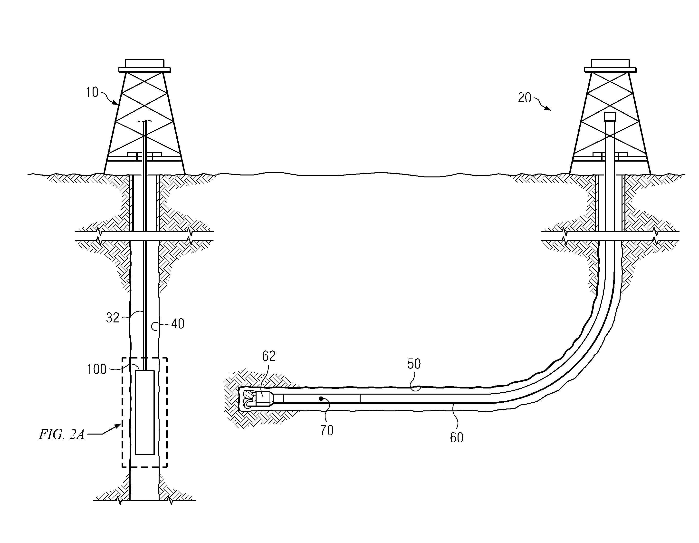
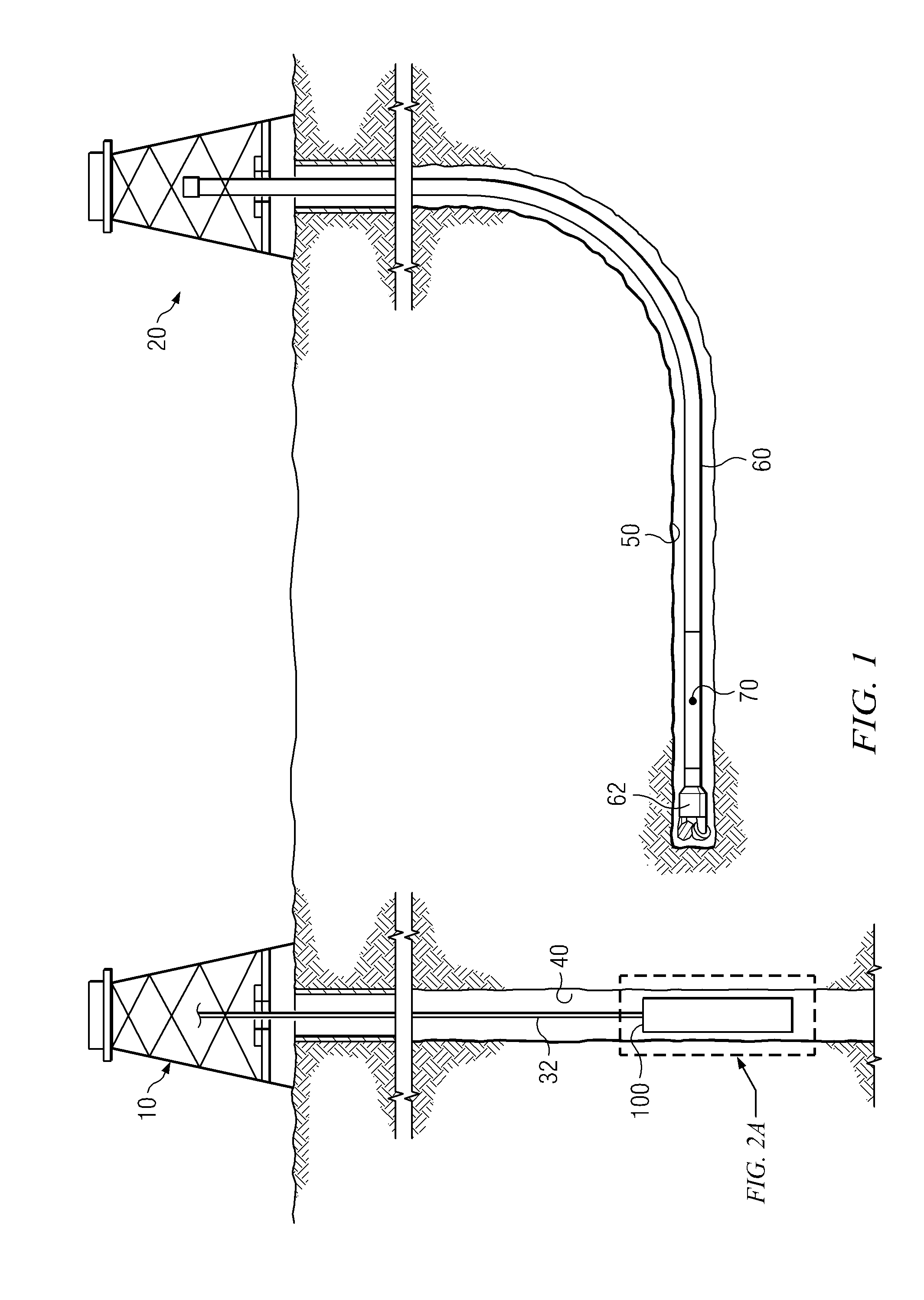
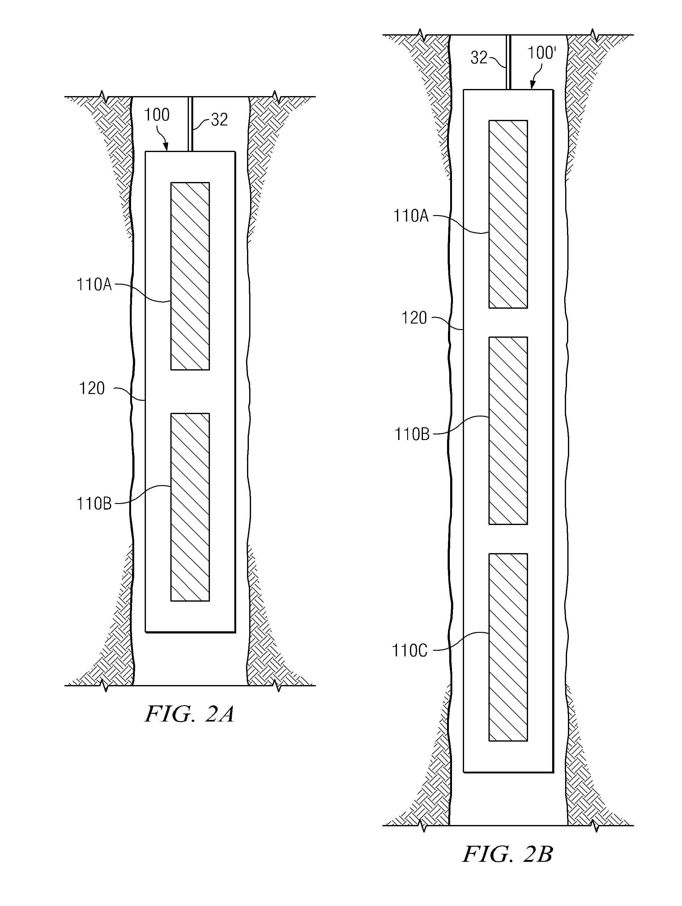
[0020]Referring now to FIGS. 1 through 6, exemplary embodiments of the present invention are depicted. With respect to FIGS. 1 through 6, it will be understood that features or aspects of the embodiments illustrated may be shown from various views. Where such features or aspects are common to particular views, they are labeled using the same reference numeral. Thus, a feature or aspect labeled with a particular reference numeral on one view in FIGS. 1 through 6 may be described herein with respect to that reference numeral shown on other views.

[0021]FIG. 1 depicts one exemplary embodiment of a horizontal to vertical well intercept operation in accordance with the present invention. In FIG. 1, first and second rigs 10 and 20 are positioned over a subterranean oil or gas formation (e.g., a coal bed—not shown). The rigs may include, for example, conventional derricks and hoisting apparatuses for lowering and raising various components into and out of corresponding wellbores 40 and 50. ...


PUM


Abstract

An electromagnetic array includes a plurality of axially spaced electromagnets deployed in a non-magnetic housing. The array further includes an electrical module, such as a diode bridge, configured to provide an electrical current having a fixed polarity to at least the first electromagnet in the array. The array may be configured to generate a magnetic field pattern having (i) a single magnetic dipole when the array is energized with an electrical current having a first polarity and (ii) at least one pair of opposing magnetic poles when the array is energized with an electrical current having the opposite polarity. The invention provides multiple independent ranging methodologies for determining the relative position between the wellbores.

Description

RELATED APPLICATIONS[0001]None.FIELD OF THE INVENTION[0002]The present invention relates generally to drilling and surveying subterranean boreholes such as for use in oil and natural gas exploration. In particular, this invention relates to an apparatus and method for making magnetic ranging measurements of a subterranean borehole.BACKGROUND OF THE INVENTION[0003]Active magnetic ranging techniques are commonly utilized in well twinning, well intercept, and well guidance applications, for example, including steam assisted gravity drainage (SAGD) and coal-bed methane (CBM) drilling applications. CBM well intercept applications commonly include an operation in which a vertical, or near vertical, borehole is intercepted with a deviated borehole (e.g., a horizontal or near horizontal borehole). Such applications commonly make use of a magnetic source deployed in the vertical (target) well and a magnetic field sensor deployed in the horizontal (drilling) well.[0004]The use of electromagne...

Claims


Application Information

Patent Timeline
Patent Type & Authority Applications(United States)
IPC IPC(8): G01B7/14
CPCE21B47/02216E21B47/0228
Inventor MCELHINNEY, GRAHAM A.MOORE, ROBERT A.
Owner SCHLUMBERGER TECH CORP
Learn More