Crimping apparatus having a crimp quality monitoring system

a crimping apparatus and quality monitoring technology, applied in the field of crimping equipment, can solve the problems of system monitoring, many unsatisfactory crimping connections, and unsatisfactory crimping connections

Active Publication Date: 2012-06-07
TYCO ELECTRONICS LOGISTICS AG (CH)
View PDF5 Cites 11 Cited by
  • Summary
  • Abstract
  • Description
  • Claims
  • Application Information

AI Technical Summary

Benefits of technology

[0006]In one embodiment, a crimping apparatus is provided that includes a ram having crimp tooling for crimping a terminal to a wire during a crimp stroke and a force sensor detecting a crimp force during the crimp stroke. The crimping apparatus also includes a controller that monitors a crimp quality of a crimp based on a frequency profile of the crimp stroke. Optionally, the controller may create the frequency profile based on a force profile using a frequency transform algorithm. The frequency transform algorithm may be a Fast Fourier Transform algorithm.
[0007]Optionally, the controller may develop a force profile based on the crimp forces detected by the force sensor, and the controller may convert the force profile to the frequency profile. The controller may analyze at least one of the force profile and the frequency profile to monitor crimp quality. The force sensor may measure the crimp force at selected intervals based on at least one of time and crimp tooling position. Optionally, the controller may determine a type of crimp defect based on the frequency profile. The controller may uti

Problems solved by technology

Ordinarily, if a terminal is not crimped to the correct crimp height for the particular terminal and wire combination, an unsatisfactory crimp connection will result.
However, many unsatisfactorily crimp connections will, nevertheless, exhibit a “correct” crimp height.
As such, systems that monitor crimp quality based on crimp height may pass defective leads from the crimping apparatus.
Such factors include using the wrong terminal or wire size, missing strands of wire, short brush, insulation in the crimp, abnormal position of the terminal, wrong wire type, incorrect stripping of insulation, and the like.

Method used


Image

  • Crimping apparatus having a crimp quality monitoring system
  • Crimping apparatus having a crimp quality monitoring system
  • Crimping apparatus having a crimp quality monitoring system

Examples


Embodiment Construction

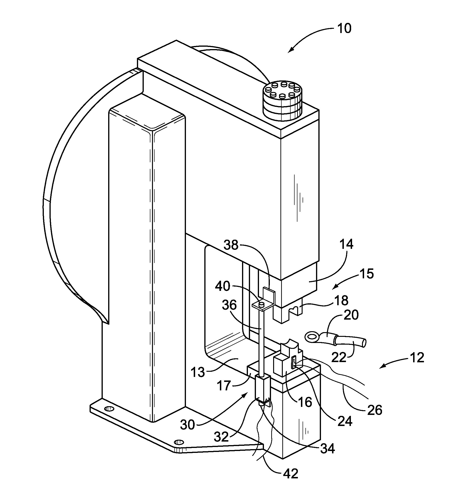
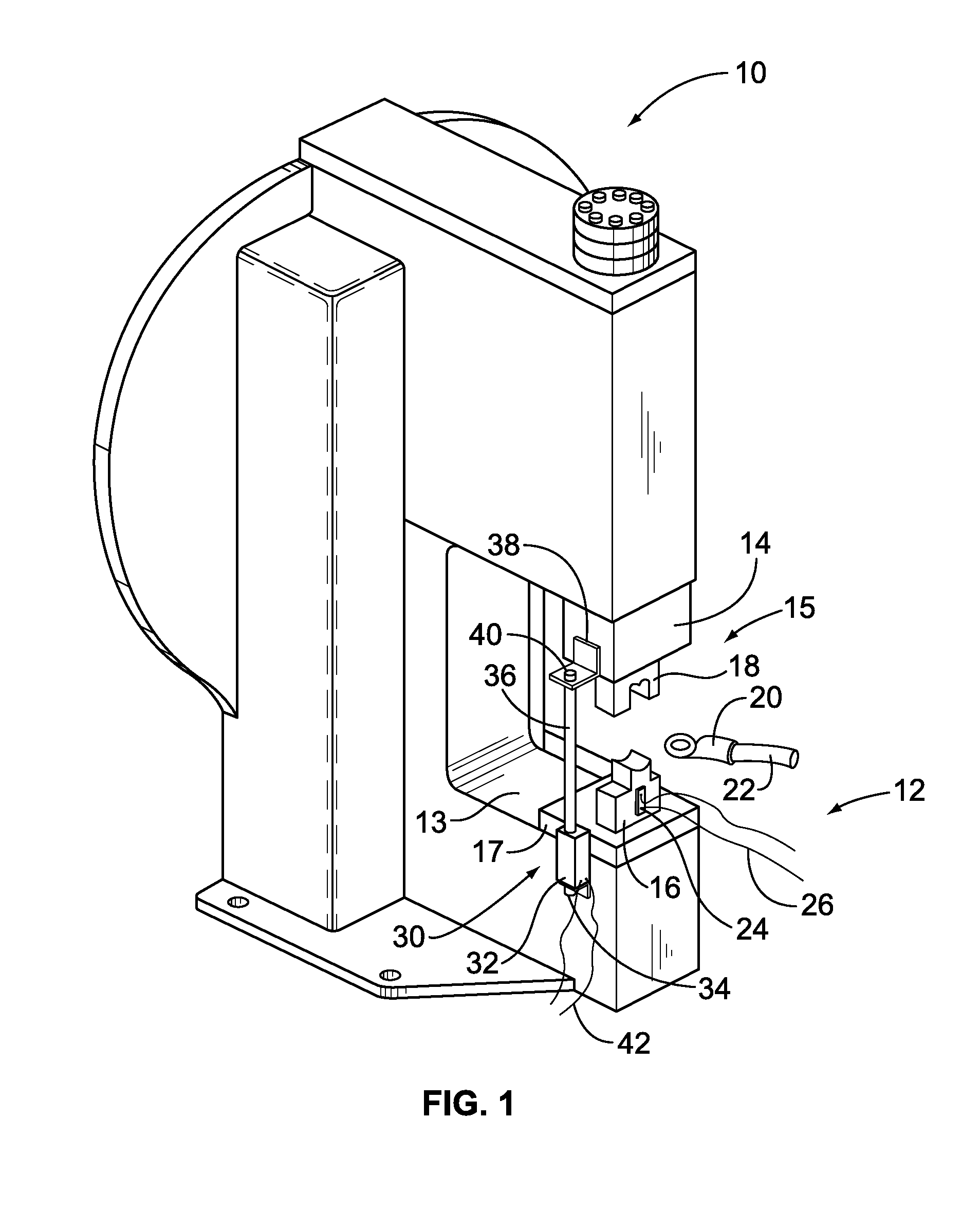
[0016]FIG. 1 illustrates an exemplary crimping apparatus 10 having a crimp quality monitoring system 12 formed in accordance with an exemplary embodiment. The crimping apparatus 10 has a base 13 and a ram 14 arranged for reciprocating opposed motion relative to the base 13. Optionally, the crimping apparatus 10 may be of the type having a flywheel and clutch arrangement for imparting the reciprocating motion to the ram 14. However, other types of crimping apparatus having a suitable ram stroke may be used in alternative embodiments. While the crimping apparatus 10 is illustrated as being an applicator, other types of crimping apparatus may be used such as a leadmaker machine, a handheld pressing tool, and the like.

[0017]The base 13 and the ram 14 each carry a mating half of crimp tooling 15. The crimp tooling 15 includes an anvil 16, which represents a fixed component of the crimp tooling 15 that is removably attached to a base plate 17. The crimp tooling 15 includes a crimper 18, w...


PUM

PropertyMeasurementUnit
Forceaaaaaaaaaa
Sizeaaaaaaaaaa
Frequencyaaaaaaaaaa

Abstract

A crimping apparatus includes a ram having crimp tooling for crimping a terminal to a wire during a crimp stroke and a force sensor detecting a crimp force during the crimp stroke. The crimping apparatus also includes a controller that monitors the crimp quality of a crimp based on a frequency profile of the crimp. Optionally, the controller may create the frequency profile based on a force profile using a frequency transform algorithm. The frequency transform algorithm may be a Fast Fourier Transform algorithm.

Description

BACKGROUND OF THE INVENTION[0001]The subject matter herein relates generally to crimping apparatus, and more particularly to crimp quality monitoring systems for crimping apparatus.[0002]Electrical terminals are typically crimped onto wires by a crimping apparatus to form a lead. The crimping apparatus has crimp tooling made up of a first part mounted to a base for supporting the electrical terminal and a second part mounted to a ram that is movable toward and away from the base for effecting the crimp. In operation, the terminal is placed on the first part of the crimp tooling, and an end of a wire is inserted into the ferrule or barrel of the terminal. The ram is caused to move toward the base through a crimp stroke, thereby crimping the terminal onto the wire.[0003]It is desirable to, and systems have been developed that, monitor the quality of the crimp. When a defective crimp is detected, the lead is discarded. Some known crimp quality monitoring systems measure crimp quality b...

Claims


Application Information

Patent Timeline
IPC IPC(8): B23Q17/00B23P21/00
CPCH01R43/0486Y10T29/49764Y10T29/53022Y10T29/49185Y10T29/53235
Inventor CHARLTON, JOHN D.NICHOLAS, KEITH L.DUBLER, ROBERT A.
Owner TYCO ELECTRONICS LOGISTICS AG (CH)
Why Eureka
Try Eureka