Knee joint prosthesis and related method

a joint and joint technology, applied in the field of knee joint prosthesis, can solve the problems of reducing the service life of the endoprosthesis, loosening of the implant, failure of the prosthesis components, etc., and achieves the effect of good tribology and wear characteristics, high degree of conformity

Active Publication Date: 2012-05-31
AESCULAP AG
View PDF65 Cites 24 Cited by
  • Summary
  • Abstract
  • Description
  • Claims
  • Application Information

AI Technical Summary

Benefits of technology

[0049]As a result of the complementary or conforming geometry of the articulation surfaces in the knee joint prosthesis of the invention, and the fact that these surfaces are formed in ceramic components, the method of the invention makes it possible to finish the articulation surfaces to such a high degree of conformity and congruence that a “run-in” period for the prosthesis no longer required once implanted in the patient. Indeed, the method of the invention has been able to produce a degree of congruence and a low-wear surface finish or surface quality that other surface finishing techniques to date have not been able to achieve with the geometries of a knee prosthesis. This surface finish exhibits, for example, a micro-geometric surface topography that is almost isotropic and has demonstrated extremely good tribology and wear characteristics.
[0050]Thus, with the above method, the bearing portion of the tibial component and the body portion of the femoral component are fully adapted to one another prior to implantation and have mating surfaces in a degree of conformity with one another not previously realisable. In this regard, the quality of the surface finish may provide the following: a form precision of 1 μm / m, a middle roughness value Ra<0.3 μm, the avoidance of surface waviness (i.e. <4 μm), and roundness of to 0.2 μm. And when considering the geometry of the articulation surfaces formed in the ceramic bearing portion and the ceramic body portion as a whole, the inventive method is able to provide diameter tolerance in the range of 0 to 50 μm (typically 10 μm), spherical deviation ≦5 μm, accuracy of fit of the components ≦1 μm, and roughness value 0.01<Ra<0.3 μm.

Problems solved by technology

The causes of the complications are numerous and include infection, wear and even failure of the prosthesis components.
One of the main causes is loosening of the implant, which occurs in about 26% of cases, and studies have shown this often to be directly associated with wear of the implant components.
Thus, the wear of the softer polyethylene components has been found to result in a reduced service life of the endoprosthesis, which is rarely more than about ten years.
Ceramic materials have the disadvantage, however, that they are relatively brittle (i.e. they have low fracture toughness), making them highly susceptible to fracture when stressed.
Such rolling contact creates localized loading of the contacting surfaces of the prosthesis, which in turn creates stress concentrations and can lead to component failure in ceramic materials.
In addition, the required level of geometric precision and surface smoothness is often not achieved in the finishing processes for ceramic components, and unevenness in the ceramic contact surfaces can similarly lead to high stress concentrations under load.
Furthermore, after sintering, the ceramic is hard and can only be processed with specialised tools, e.g. incorporating diamond abrasives.
Consequently, the requisite degree of precision in the dimensioning and finishing of the ceramic components is simply not possible without the ceramic material undergoing a machine finishing procedure.
The kinematics and the relative complex geometries of the human knee joint, in combination with the requirements of implant quality, have impeded the application of ceramic materials in knee joint endoprostheses to date.
That is, suitable processing technologies for generating and finishing the complex geometries required for a practically viable knee joint prosthesis formed of ceramic material have not been available.
Such a joint, however, provides the articulation of a fixed hinge, which is biomechanically quite unsuitable for a human knee joint.
This prosthesis, however, still suffers from the problem that the femoral component is designed to provide a rolling motion relative to the tibial component, and this leads to stress concentrations between the engaging surfaces.

Method used


Image

  • Knee joint prosthesis and related method
  • Knee joint prosthesis and related method
  • Knee joint prosthesis and related method

Examples


Embodiment Construction

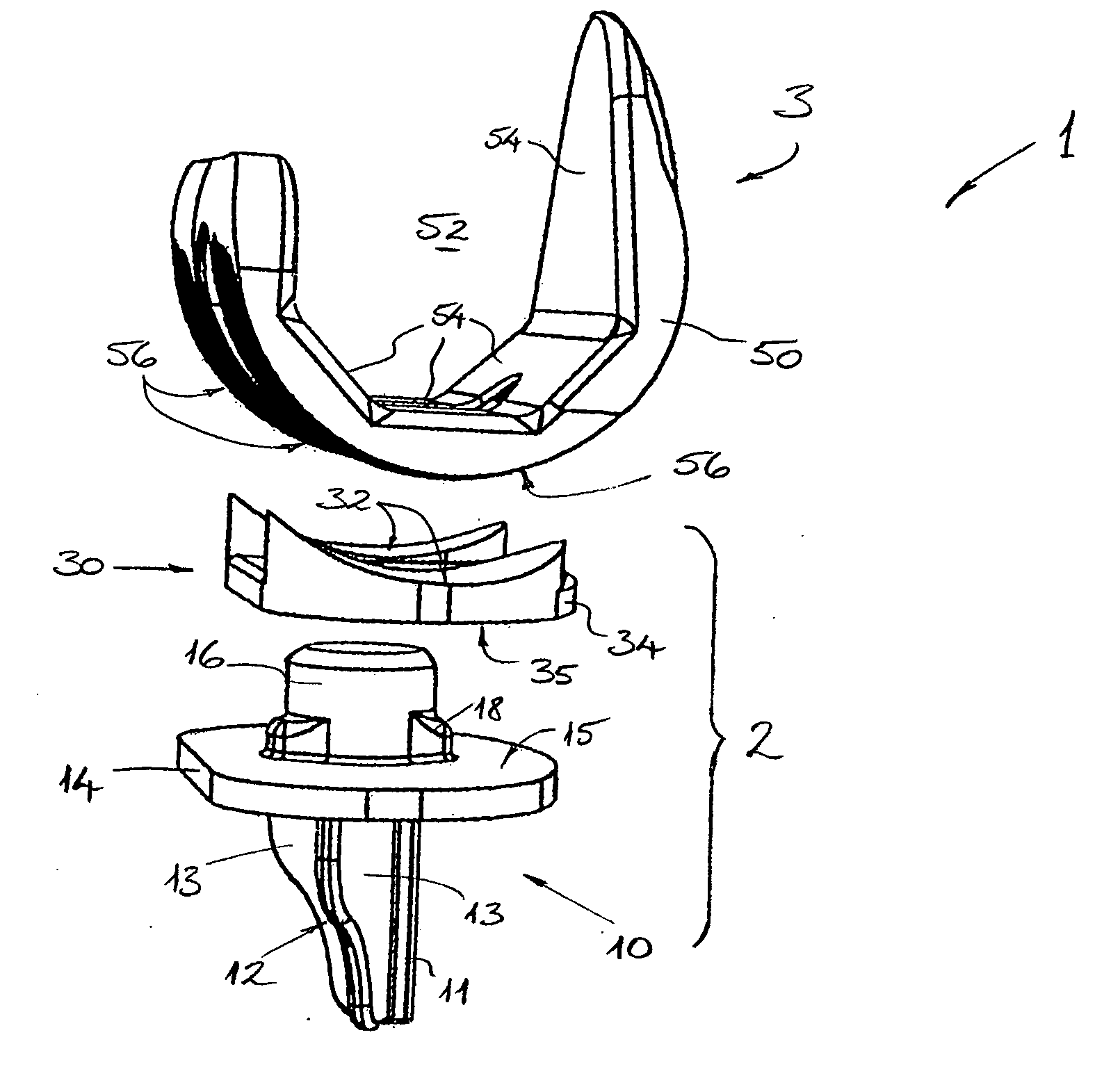
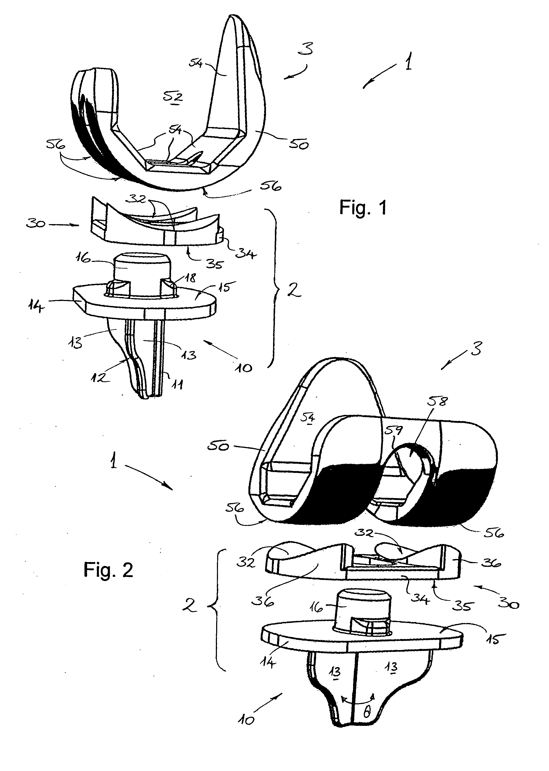
[0099]The Referring firstly to FIGS. 1 and 2 of the drawings, the primary components of a knee joint prosthesis 1 according to a preferred embodiment of the invention are shown in exploded perspective views. As is clearly apparent, the knee joint prosthesis 1 in this embodiment is comprised of three discrete or separate parts. The lower part and the middle part in FIGS. 1 and 2 combine to form a tibial component 2 for attachment at an end of a tibia T of a patient, while the upper part forms a femoral component 3 which is designed to be attached at an end of a femur F of the patient.

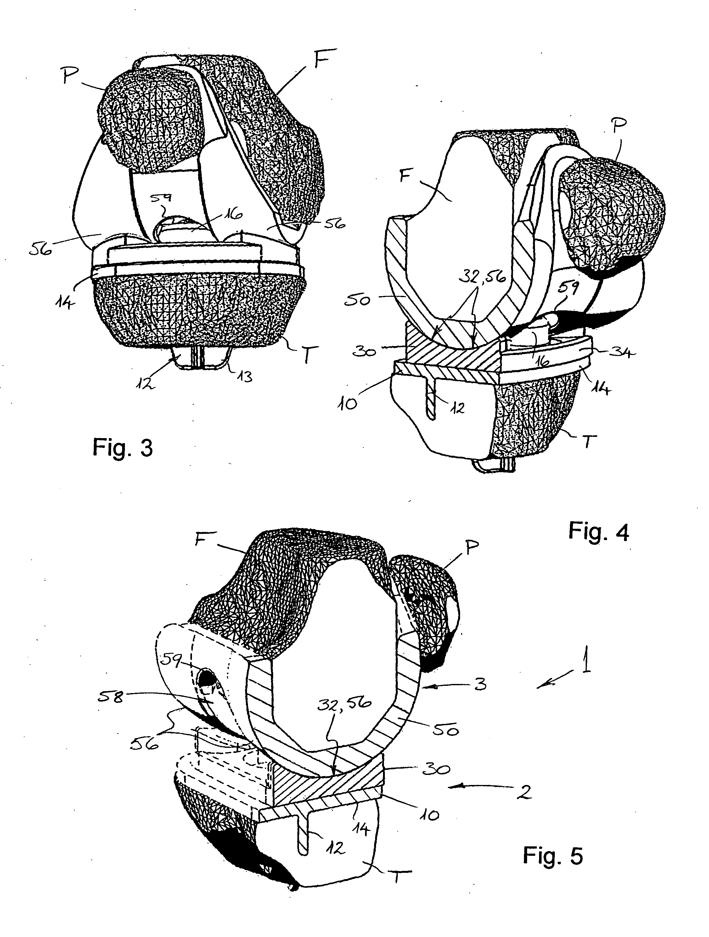
[0100]With reference to FIGS. 3 to 5 of the drawings, the implanted or in-use orientation and interrelationships of the tibial component 2 and the femoral component 3 of the knee joint prosthesis 1 of the invention are illustrated. Furthermore, in addition to the tibia T and femur F, the patella P (commonly called the “knee cap”) is illustrated in relation to the components of the prosthesis.

[0101]Consid...


PUM

PropertyMeasurementUnit
angleaaaaaaaaaa
angleaaaaaaaaaa
frequencyaaaaaaaaaa

Abstract

The present invention relates to a knee joint prosthesis having a tibial component and a femoral component. The tibial component includes a fixation portion fixed to an upper end of a prepared tibia and a ceramic bearing portion presenting articulation surface(s). The femoral component is fixed to a lower end of a prepared femur and comprises a ceramic body portion presenting articulation surface(s). The respective articulation surfaces of the tibial and femoral components are configured for essentially congruent engagement over a full range of movement of the prosthesis, and the bearing portion of the tibial component is adapted for movement relative to the fixation portion. Also disclosed is an apparatus and a method for finishing articulation surfaces of ceramic components of a knee joint prosthesis, including the steps of combining the ceramic bearing portion and the ceramic body portion, and imparting relative movement to the bearing portion and/or the body portion.

Description

FIELD OF THE INVENTION[0001]The present invention relates to a knee prosthesis and to a method of manufacturing components for such a prosthesis. In particular, the present invention provides a knee joint prosthesis, as well as individual components of the prosthesis. In addition, the invention provides a method of finishing articulation surfaces of the components of the knee joint prosthesis, as well as an apparatus for performing that method.BACKGROUND OF THE INVENTION[0002]Knee joint prostheses are typically employed in patients suffering serious afflictions of the knee joint, e.g. caused by diseases such as osteoarthritis. Such prostheses typically involve a partial or full replacement of the knee joint, and the components of the prosthesis are fully implanted within the body of the patient. In other words, these knee joint prostheses are generally endoprostheses.[0003]Each year over 100,000 knees are endoprosthetically treated in Germany alone, and of the knee joint prostheses ...

Claims


Application Information

Patent Timeline
Patent Type & Authority Applications(United States)
IPC IPC(8): A61F2/38B23P11/00
CPCA61F2/3094A61F2/3868A61F2/3886A61F2/468A61F2002/30365A61F2002/30369Y10T29/49826A61F2002/30934A61F2220/0025A61F2220/0033A61F2310/00203A61F2310/00239B24B31/003A61F2002/30528A61F2002/3895
Inventor RICHTER, BERNAHURSCHLER, CHRISTOFOSTERMEIER, SVEN
Owner AESCULAP AG
Why Eureka
Try Eureka