
Torque wrench and kit for implant dentistry

a technology for tooth extraction and torque wrench, which is applied in the field of tooth extraction torque wrench and kit for tooth extraction, can solve the problems of screw or abutment loosening, too much torque may over stress or strip the bone, and action offers less control, so as to achieve little or no maintenance

Inactive Publication Date: 2012-05-24
WERNER EXTRUSION SOLUTIONS
View PDF5 Cites 0 Cited by
  • Summary
  • Abstract
  • Description
  • Claims
  • Application Information

AI Technical Summary

Benefits of technology

"This patent describes a unique hand-operated driving tool for installation of threaded supports, abutments, and screws in implant dentistry. The tool has a low profile and is suitable for use in clinical spaces. It also includes a torque limited wrench for applying a selected maximum torque during installation. The system includes disposable elements for exacting torque control reliability and little or no maintenance. The torque wrench is attached to a driver for threadably installing supports, abutments, and screws, and it has a cylindrical member with a spring and rotatable ball for securely tightening components to a predetermined torque. The system also includes a kit with multiple torque wrenches and drivers for different support members. The technical effects of this invention include improved precision and reproducibility in tightening components to a specified torque, cost-effectiveness, and ease of use in dental restoration systems."

Problems solved by technology

Too much torque may over stress or strip the bone, dental screw, implant or abutment.
Insufficient torque will not ensure a sufficient securement into the bone, possibly causing the screw or abutment to loosen, requiring a follow up re-tightening procedure.
The ratchet action offers less control because it interferes with the “feel” or tactile sensitivity of the installation, and the ratcheting movement introduces undesirable instability in a sensitive procedure.
In ratcheting, the dentist is also unable to get the desired tactile feedback regarding torque resistance of the meshing threads, etc.
The use of screwdriver bits on electrical dental handpieces is likewise undesirable because of the complete loss of tactile sensitivity with the attendant risk of either breaking the screw or spinning the implant in the bone.

Method used


Image

  • Torque wrench and kit for implant dentistry
  • Torque wrench and kit for implant dentistry
  • Torque wrench and kit for implant dentistry

Examples


Embodiment Construction

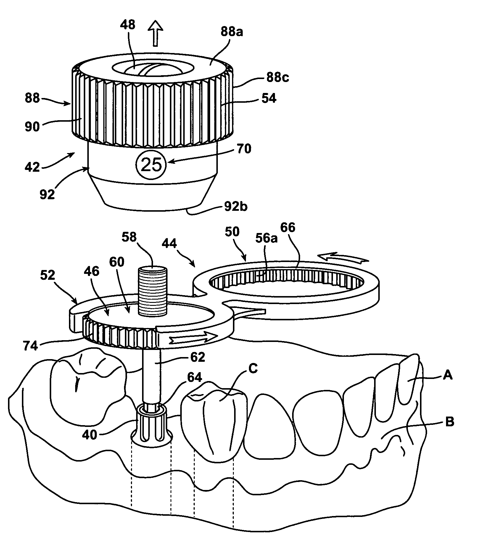
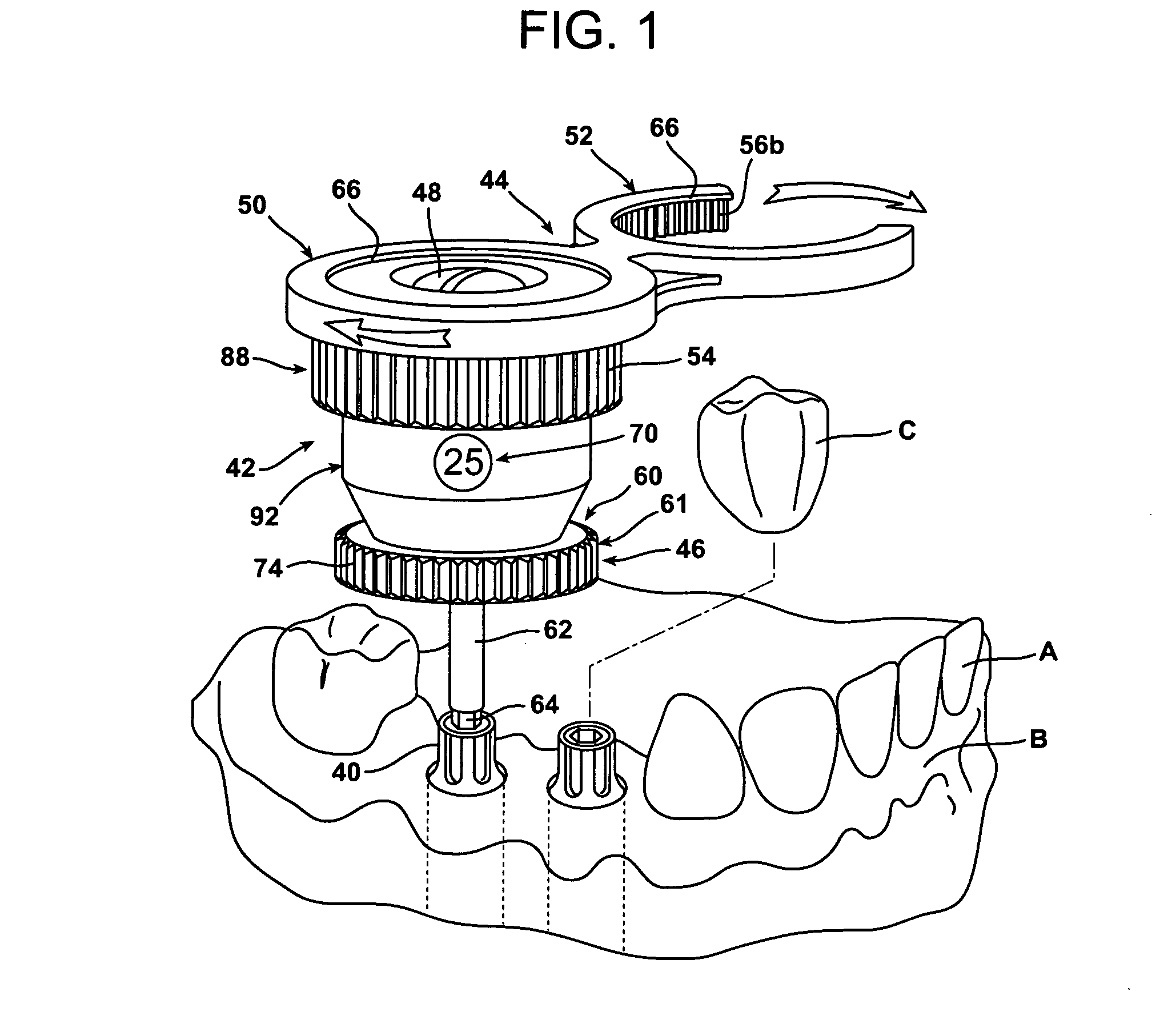
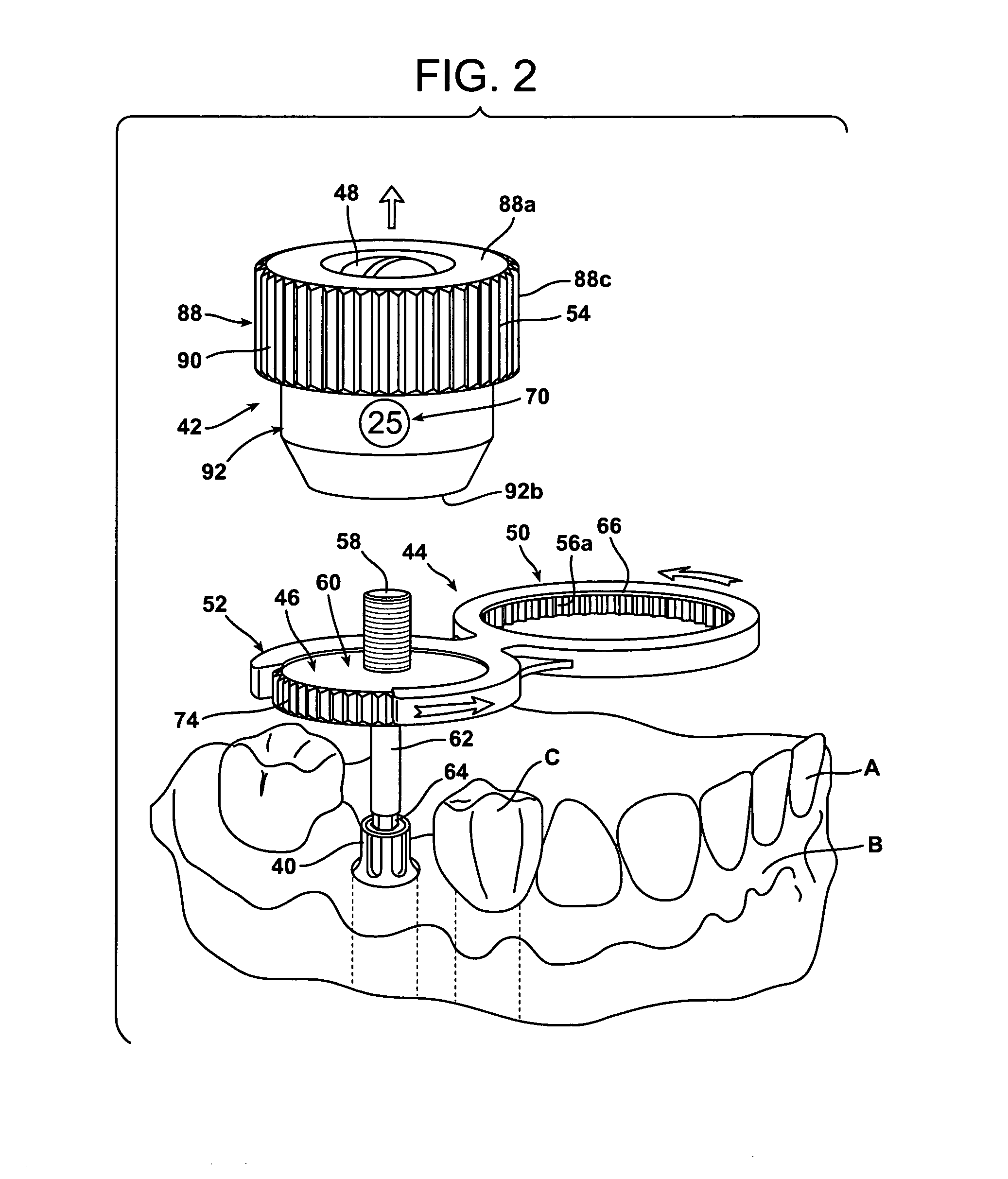
[0059]Referring to FIG. 1, this invention relates to fabricating and / or installing a prosthesis into patients. The prosthesis is usually a temporary healing cap or permanent dental crown C. A hollow receiving device or “implant” is implanted into a patient, usually into the patient's jaw bone (alveolar). A support device or “abutment” is fitted into the implant and extends upwardly away from the jaw bone for receiving a healing cap and / or a permanent prosthesis.

[0060]Again referring to FIG. 1, the present invention is directed to a dental driver tool, i.e., torque wrench 42, for manually driving an abutment 40 onto an implant that was placed in a prepared surgical site in a jawbone B of a patient. The abutment 40 is screwed into the implant and the crown C placed over the abutment 40. A number of materials can be used for making the abutment 40, including gold or titanium. The crown C is shown just prior to placement or cementing onto the abutment adjacent the existing teeth A. More...


PUM


Abstract

A wrench for a installing a support member for a prosthesis including a body, rotating cylinder in the center, and cap. The cylinder has a cap on one end and a driver on the other. The bottom of the cap has radially disposed ridges and grooves. The body has bores therein, each with a spring and rotatable ball. Each ball protrudes from a bore and is in contact with a groove.When the cap is rotated each ball is in a groove and the cap, body and driver rotate together, to install the support member. When a maximum torque is obtained, each ball is depressed causing the cap to rotate preventing further installation of the member.A kit includes several wrenches and drivers, each wrench having a different maximum torque and each driver having a different tip configuration.

Description

BACKGROUND OF THE INVENTION[0001]1. Field of the Invention[0002]The present invention relates to the field of dental implantology and, more specifically, to a dental driver tool, i.e., a torque wrench, for manually driving a dental implant support member into an implant that was placed into a surgical site in a jawbone of a patient. Broadly, this invention relates to a torque wrench and driver system that can be used with most commercially available implant systems. More specifically, this invention relates to a torque wrench for applying a selected (predetermined) maximum torque during installation of a dental implant support, e.g., abutments and screws, into a dental implant, and a kit that includes a plurality of such torque wrenches with differing predetermined maximum torques, a mating wrench, and a plurality of interchangeable drivers with various configurations of tips for use with different configurations of supports, abutments and screws.[0003]2. Related Art[0004]Implant sy...

Claims


Application Information

Patent Timeline
Patent Type & Authority Applications(United States)
IPC IPC(8): A61C8/00
CPCA61C8/0089
Inventor RUFF, JEFFREY
Owner WERNER EXTRUSION SOLUTIONS
Learn More