
Image processing method for determining depth information from at least two input images recorded with the aid of a stereo camera system

a stereo camera and image processing technology, applied in image analysis, image enhancement, instruments, etc., can solve the problems that the method has not yet been used in the field of signal processing, and achieve the effects of reducing computational effort, reducing geometric distortion, and reducing processing costs

Inactive Publication Date: 2012-05-24
ROBERT BOSCH GMBH
View PDF2 Cites 74 Cited by
  • Summary
  • Abstract
  • Description
  • Claims
  • Application Information

AI Technical Summary

Benefits of technology

[0017]The previously mentioned flaws of the known methods are advantageously completely eliminated by the image processing method according to the present invention. The image processing method according to the present invention for ascertaining stereo video disparities or the disparity on the basis of a statistical rank correlation measure does not have any of the mentioned limitations. The used parameter-free or non-parametric statistics of the data is invariant compared to monotonous, non-linear transformations. Parameter-free statistics deals with parameter-free statistical models and parameter-free statistical tests. Other conventional designations are non-parametric statistics or distribution-free statistics. The model structure is not previously defined. No assumptions regarding the probability distribution of examined variables are made. A rank correlation coefficient or a rank correlation measure is a parameter-free measure for correlations which may be used to measure the level of agreement between two stochastic variables without making assumptions regarding the parametric structure of the probability distribution of the variables. The method allows implementation on currently embedded systems, e.g. field programmable gate arrays (FPGA), dense estimation of disparities for generally more than 90% of the relevant image points, robust estimation of disparities with an outlier rate of generally less than 1% and a disparity estimation with an accuracy in the range of subpixels. In the image processing method according to the present invention, a statistical measure or a statistical metric is used instead of deterministic distance measures. The use of a statistical rank correlation is significantly mathematically motivated since the method may be attributed to a normalized correlation coefficient.
[0018]The input images may be rectified, partially rectified, or not rectified. Rectification or correction generally refers to the elimination of geometric distortions in image data, e.g., due to non-ideal imaging properties of the optics or small geometric manufacturing tolerances of the imager.
[0019]It is particularly advantageous when the Kendall's-Tau rank correlation coefficient or a variant of this coefficient is used as the non-parametric statistical rank correlation measure. The Kendall rank correlation measure is described for example in H. Abdi, Kendall rank correlation, in N. J. Salkind (Ed.): “Encyclopedia of Measurement and Statistics” Thousand Oaks (Calif.), 2007 [3] as introduced in 1938 in mathematical statistics. However, due to the relatively high computational effort for high-dimensional data, the method has not yet been used for practical implementations in the area of signal processing. The high performance of modern embedded systems and the application-specific design of the image processing method according to the present invention now allow use in the described and related application fields.

Problems solved by technology

However, due to the relatively high computational effort for high-dimensional data, the method has not yet been used for practical implementations in the area of signal processing.

Method used


Image

  • Image processing method for determining depth information from at least two input images recorded with the aid of a stereo camera system
  • Image processing method for determining depth information from at least two input images recorded with the aid of a stereo camera system
  • Image processing method for determining depth information from at least two input images recorded with the aid of a stereo camera system

Examples


Embodiment Construction

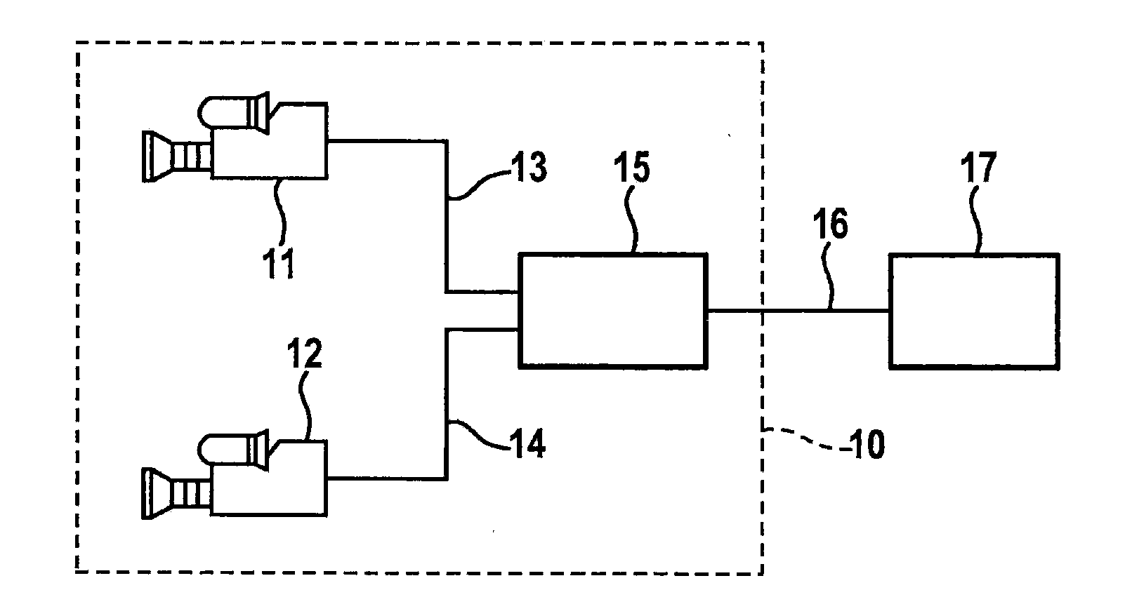
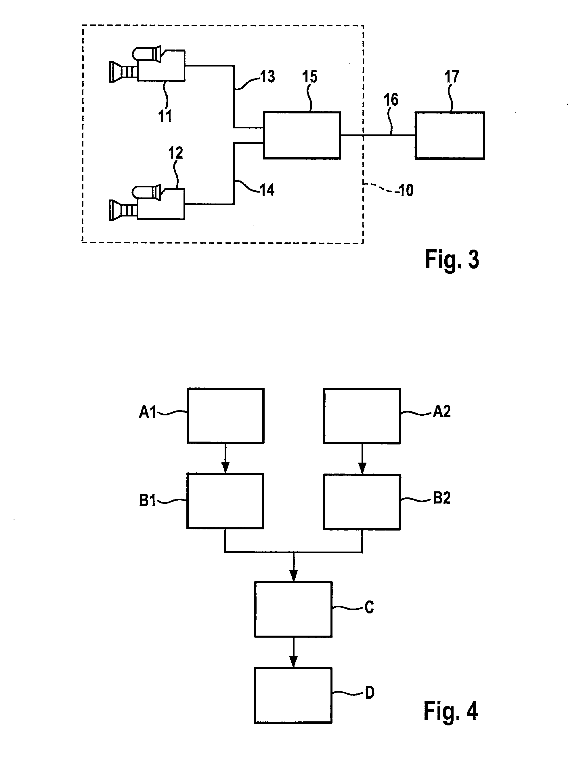
[0034]FIG. 3 shows a stereo camera system configured as a stereo video system 10 having two image sensors 11 and 12, two image sensor signal lines 13, 14, an evaluation unit or image processing device 15, an output signal line 16 and a subsequent system 17. For example, CCD or CMOS cameras or thermographic devices or the like may be used as image sensors 11, 12. Both image sensors 11, 12 are situated in such a way that they reproduce the same scenes but from a slightly different viewing angle. Image sensors 11, 12 transmit images of the observed scene to image processing device 15. On output signal line 16, image processing device 15 generates an output signal, which is transmitted electrically, digitally, acoustically, and / or visually for display, information, and / or saving to subsequent system 17. In the present exemplary embodiment, the subsequent system is a driver information system 17 of a vehicle (not shown) having stereo video system 10. In additional exemplary embodiments, ...


PUM


Abstract

An image processing method is described for determining depth information from at least two input images recorded by a stereo camera system, the depth information being determined from a disparity map taking into account geometric properties of the stereo camera system, characterized by the following method steps for ascertaining the disparity map: transforming the input images into signature images with the aid of a predefined operator, calculating costs based on the signature images with the aid of a parameter-free statistical rank correlation measure for ascertaining a cost range for predefined disparity levels in relation to at least one of the at least two input images, performing a correspondence analysis for each point of the cost range for the predefined disparity levels, the disparity to be determined corresponding to the lowest costs, and ascertaining the disparity map from the previously determined disparities.

Description

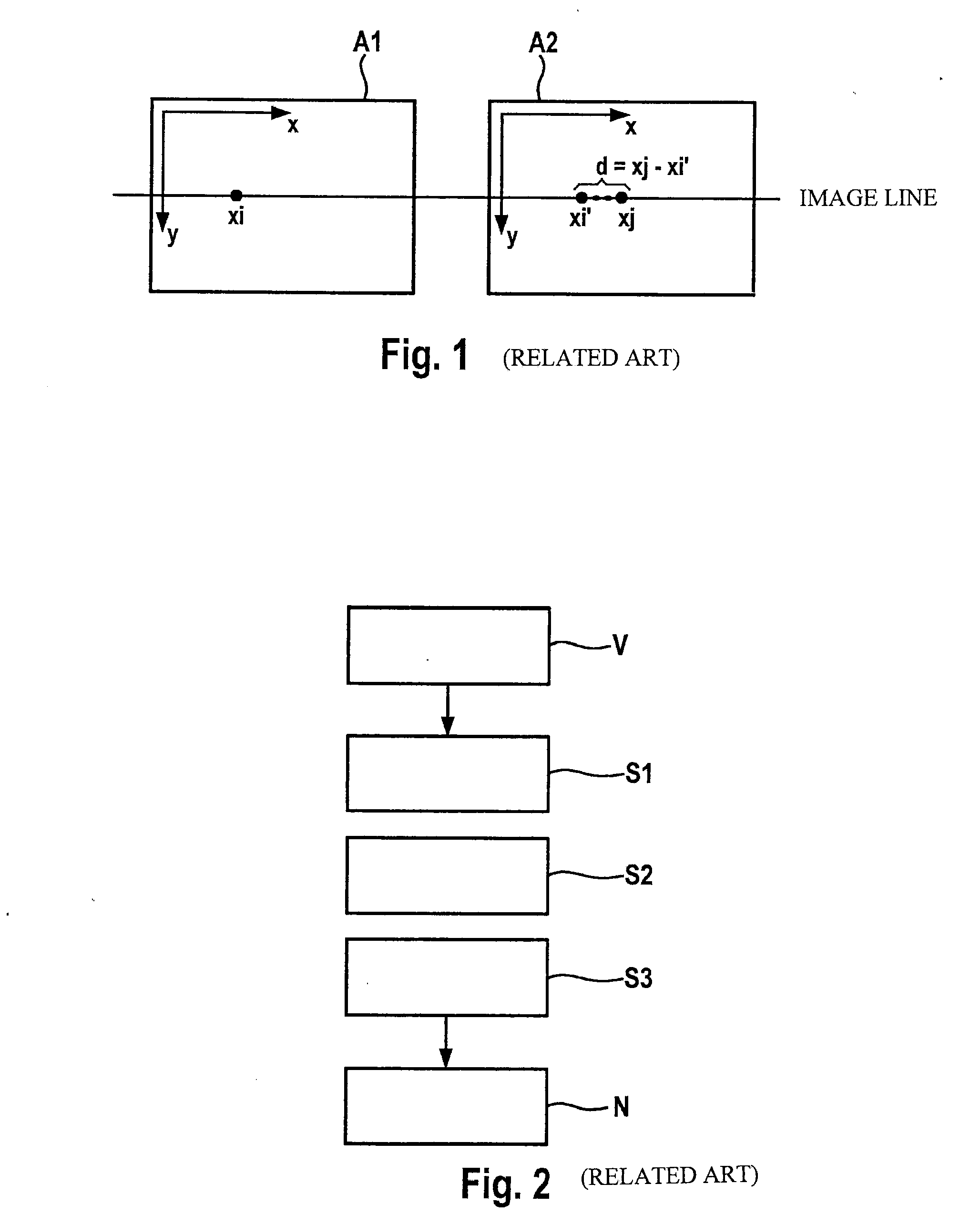
FIELD OF THE INVENTION[0001]The present invention relates to an image processing method for determining depth information from at least two input images recorded with the aid of a stereo camera system, the depth information being calculated from a disparity map taking into account geometric properties of the stereo camera system. Moreover, the present invention relates to a computer program, a computer program product, and a device for executing such a method.BACKGROUND INFORMATION[0002]Depth calculation on the basis of two stereo images is a standard problem in image processing and numerous algorithms are known for resolving this problem. Disparities d between time-synchronized and rectified stereo image pairs or stereo video image pairs are determined with the aid of stereo evaluation methods. As is apparent from FIG. 1, disparity d is defined as a one-dimensional displacement vector in the direction of the image line and indicates corresponding image point xj in right image A2 ba...

Claims


Application Information

Patent Timeline
IPC IPC(8): H04N13/02G06K9/00
CPCG06T2207/10012G06T7/0075G06T7/593
Inventor VON ZITZEWITZ, HENNINGNIEHSEN, WOLFGANGWENDT, AXEL
Owner ROBERT BOSCH GMBH
Learn More