
Determining an acoustic coupling between a far-end talker signal and a combined signal

a far-end talker and combined signal technology, applied in the direction of line-transmission, electrical equipment, interconnection arrangements, etc., can solve the problems of insufficient estimation of acoustic coupling, increased difficulty in determining the acoustic coupling, so as to improve the determination of an acoustic coupling and the effect of better estimation of the acoustic coupling

Active Publication Date: 2011-10-20
MEDIATEK INC
View PDF10 Cites 5 Cited by
  • Summary
  • Abstract
  • Description
  • Claims
  • Application Information

AI Technical Summary

Benefits of technology

[0007]In a further embodiment, the envelope of the combined signal and the envelope of the far-end talker signal are derived from a power measurement for the combined signal and the far-end talker signal, respectively, on a block basis. This method is advantageous for signals with a slow-varying envelope like e.g. speech, and can be implemented very efficiently on certain DSP platforms.
[0009]In a further embodiment, the predetermined time interval comprises a multiplicity of a time interval between the successive samples of the far-end talker signal, wherein sampling of the combined signal is aligned with sampling of the far-end talker signal. In this way the acoustic coupling can be determined on a block basis (i.e. blocks of samples). This allows to make an update of the acoustic coupling only once per block and thus provides computational reduction.
[0014]a subtraction circuit for determining the residual signal being a difference between the output signal of the adaptive filter and the changes in the envelope of the combined signal. The advantage of using the adaptive filter is that with such a (simple) adaptive filter a robust estimate of the acoustic path can be obtained.

Problems solved by technology

If also the near-end talker signal is present, then problems can occur, since the adaptive filter will diverge due to the presence of the near-end talker signal.
If the far-end talker signal and the near-end talker signal are correlated these problems are more severe.
However, for double talk situations this acoustic coupling is estimated too large, such that the decrease in the step-size of the adaptive filter becomes too small and the adaptive filter diverges from its optimum solution.

Method used


Image

  • Determining an acoustic coupling between a far-end talker signal and a combined signal
  • Determining an acoustic coupling between a far-end talker signal and a combined signal
  • Determining an acoustic coupling between a far-end talker signal and a combined signal

Examples


Embodiment Construction

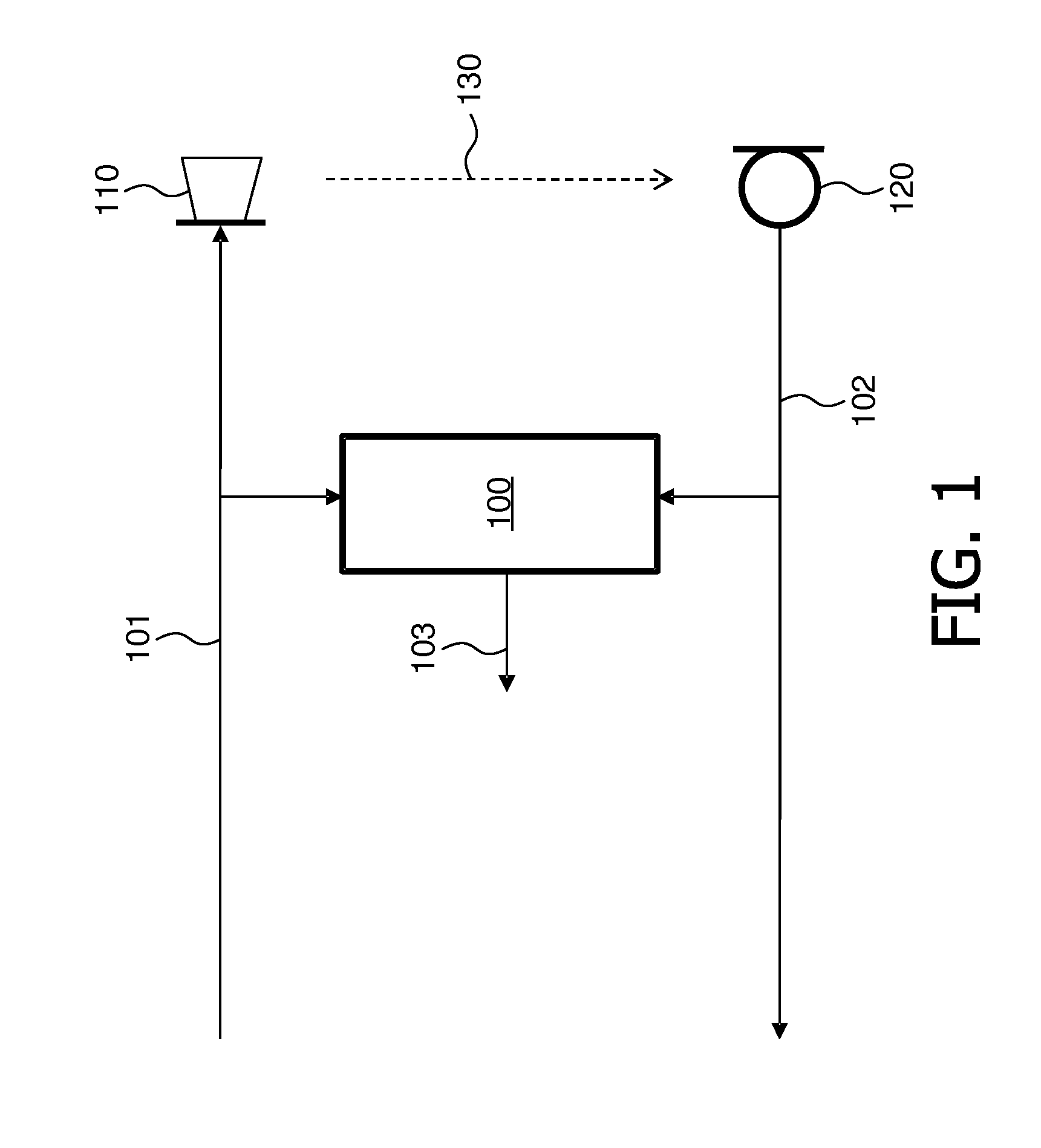
[0026]FIG. 1 shows schematically an embodiment of a device 100 for determining an acoustic coupling 103 according to the invention between a loudspeaker 110 and a microphone 120. The loudspeaker 110 is reproducing the far-end talker signal 101. The microphone 120 is picking-up a combined signal 102 comprising an echo of the far-end talker signal 101 and a near-end talker signal. The acoustic coupling phenomenon between the loudspeaker 110 and the microphone 120 is symbolically depicted by the arrow 130. The acoustic coupling 103 is derived from a ratio of changes in an envelope of the combined signal 102 to changes in the envelope of the far-end talker signal 101 in a predetermined time interval. The derived acoustic coupling is outputted by the device 100 in the form of a signal 103.

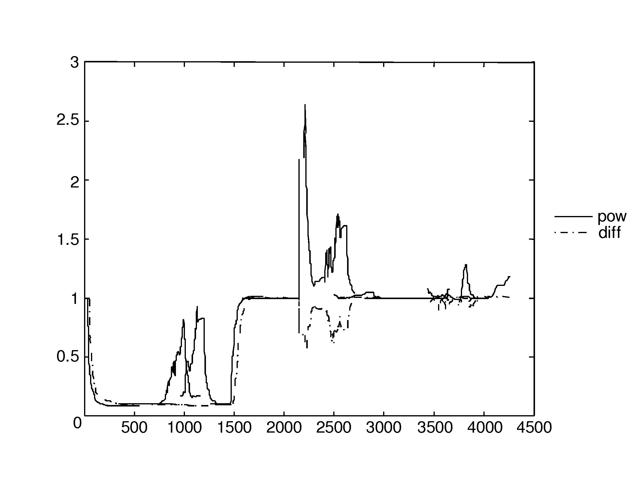
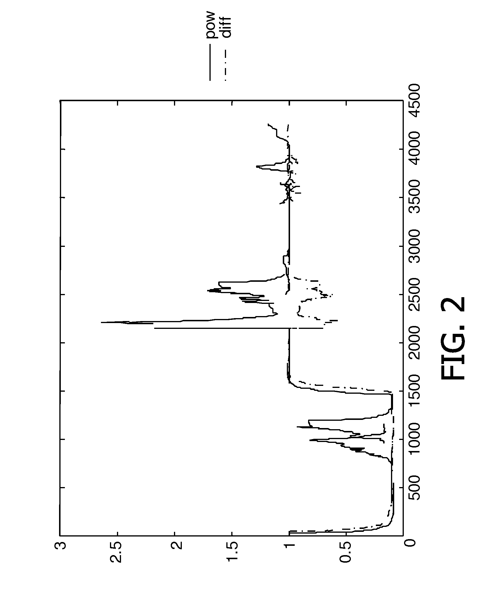
[0027]FIG. 2 shows a plot that illustrates an effect of deriving the acoustic coupling 103 from the ratio of the changes in the envelope of the combined signal 102 to the changes in the envelope of the ...


PUM


Abstract

The present invention provides an improved determination of an acoustic coupling between a loudspeaker (110) and a microphone (120), which results in a better estimate of the acoustic coupling during double talk. This is achieved in a device (100) for determining an acoustic coupling between a far-end talker signal (101) as produced by the loudspeaker (110) and a combined signal (102), which comprises an echo of the far-end talker signal and a near-end talker signal, as picked up by the microphone (120), in which the acoustic coupling is derived from a ratio of changes in an envelope of the combined signal (102) to changes in the envelope of the far-end talker signal (101) in a predetermined time interval. In this way the systematic error during double talk (an estimation of the acoustic coupling that is too large) is not present anymore or at least strongly reduced.

Description

FIELD OF THE INVENTION[0001]The invention relates to a device for determining an acoustic coupling between a far-end talker signal and a combined signal that comprises an echo of the far-end talker signal and a near-end talker signal. The invention also relates to a method for determining an acoustic coupling between a far-end talker signal and a combined signal. Furthermore, the invention relates to an acoustic echo canceller, a webcam device, a video conferencing system, and hands-free telephone terminal.BACKGROUND OF THE INVENTION[0002]In full-duplex hands-free communication system nowadays always Acoustic Echo Cancellers (AECs) are used. A crucial component of such an AEC is an adaptive filter, often referred to as an echo filter that models a physical path between a loudspeaker and a microphone and tries to predict an echo on the microphone caused by the loudspeaker. A signal of a far-end talker on the opposite side is amplified and fed to the loudspeaker. The echo is generated...

Claims


Application Information

Patent Timeline
Patent Type & Authority Applications(United States)
IPC IPC(8): H04B3/20
CPCH04M9/082H04M9/08H04R3/02
Inventor JANSSE, CORNELIS PIETERVAN STUIVENBERG, LEON C.A.
Owner MEDIATEK INC
Learn More