
Hinge device and electronic device using the same

Active Publication Date: 2012-05-17
SHIN ZU SHING
View PDF4 Cites 6 Cited by
  • Summary
  • Abstract
  • Description
  • Claims
  • Application Information

AI Technical Summary

Benefits of technology

[0014]The hinge device is unified in one integrated part and is structurally, physically and mechanically superior to a conventional hinge device so as to overcome the shortcomings and mitigate or obviate the problems of the conventional hinge device.
[0021]The strengths are higher than that of conventional non-ferromagnetic stainless steel or zinc alloy and the hardness thereof lower than that of amorphous metal. The hinge device in accordance with the present invention not only provides higher strength and hardness than non-ferromagnetic stainless steel, but also resolves the shortcoming that parts made from amorphous metal are too hard to be processed.
[0024]With the foregoing structure, the present invention provides a hinge device that may be fast and easily made as a single integrated part with a metal injection molding process. Comparing with a conventional hinge device, said hinge device significantly reduces manufacturing and assembly costs and is easier to make or design.

Problems solved by technology

The zinc alloy is a low-strength material and parts made from zinc alloy thus easily abrade away with time and unwanted gaps are formed between parts that eventually lead to disorder.
However, being limited by the original shape of the stainless steel sheet and the stamping process, there is little freedom in designing the shapes of the parts.
Furthermore, 304 and 316L series stainless steels do not provide enduring strength.
420L series stainless steel, though having high strength, is highly ferromagnetic and may interfere with the operation of the electronic device.
Thus 420L series stainless steel is not suitable for making a hinge device for use in the electronic device.
Though the molded parts are high in strength and hardness, are low in precision and require further high-precision process to achieve applicable precision.
The high-strength and high-hardness of said parts turn out to be obstacles for the high-precision process, and inevitably lead to longer processing time, high wear rate of bits and thus low yield ratio and high cost.
However, the independent hinge member and the sliding plate are respectively attached to the body and the screen with fasteners, which increases parts number as well as complexity that lead to high manufacturing cost and high assembly cost.

Method used


Image

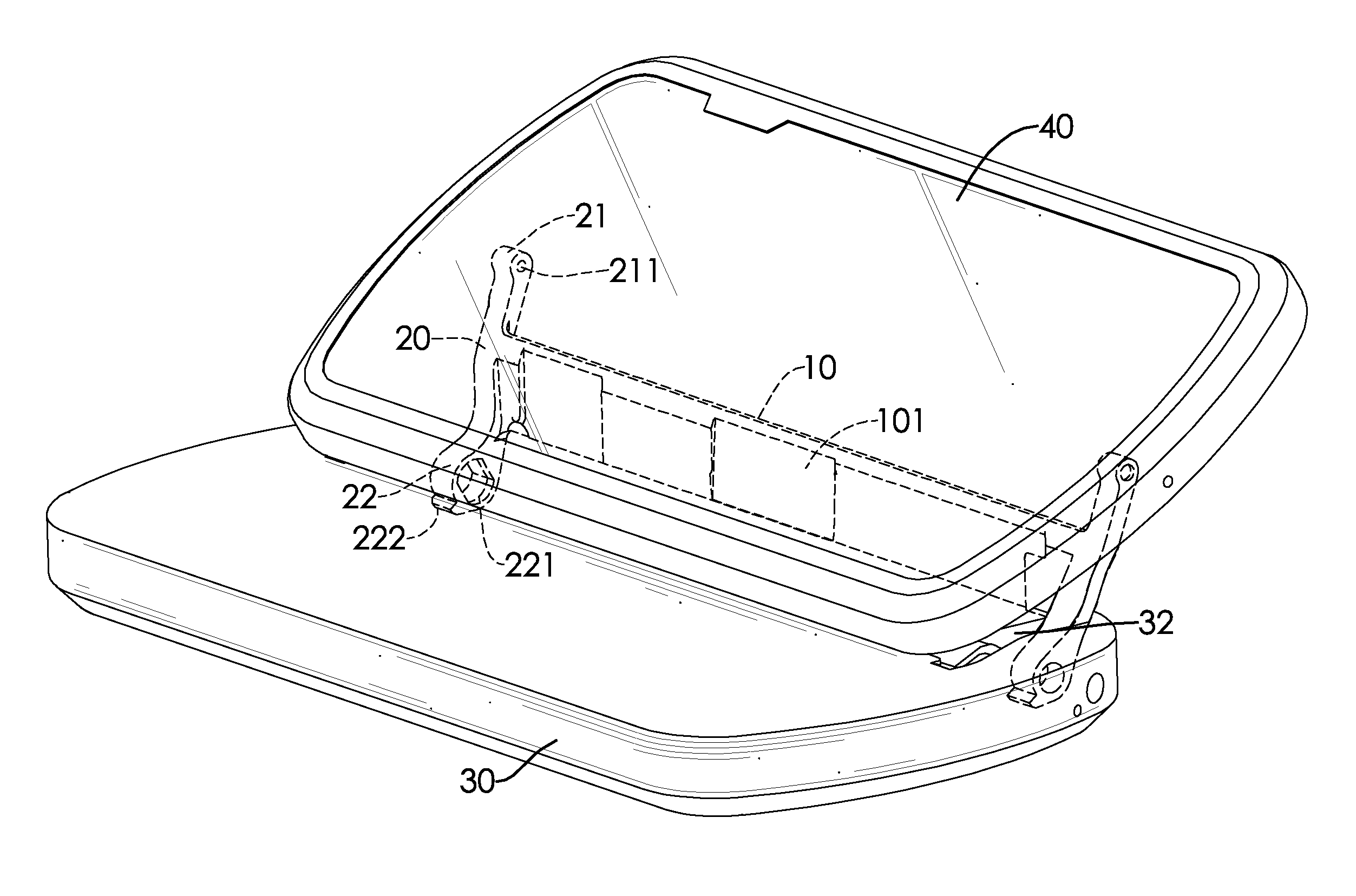
  • Hinge device and electronic device using the same
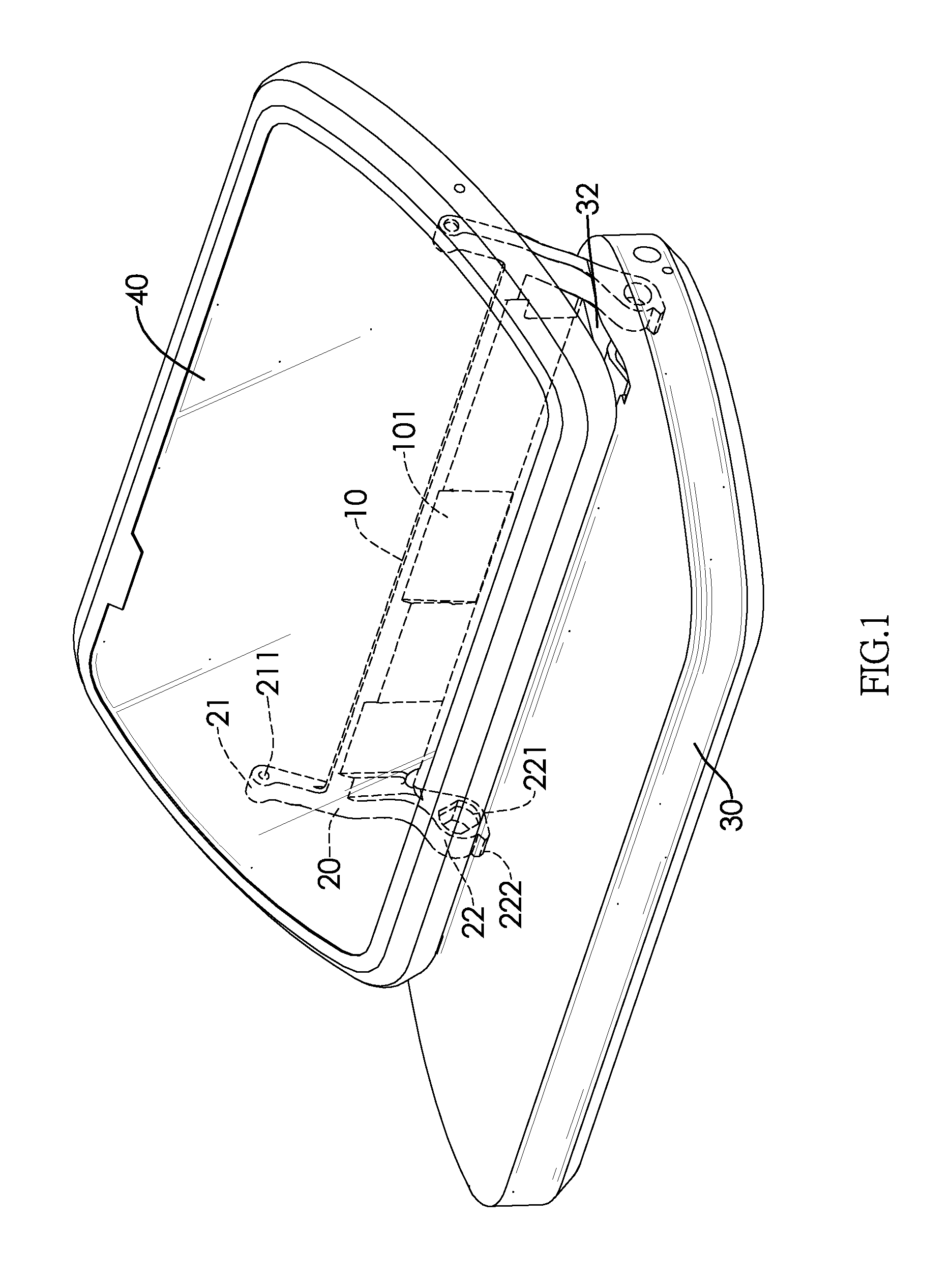
  • Hinge device and electronic device using the same
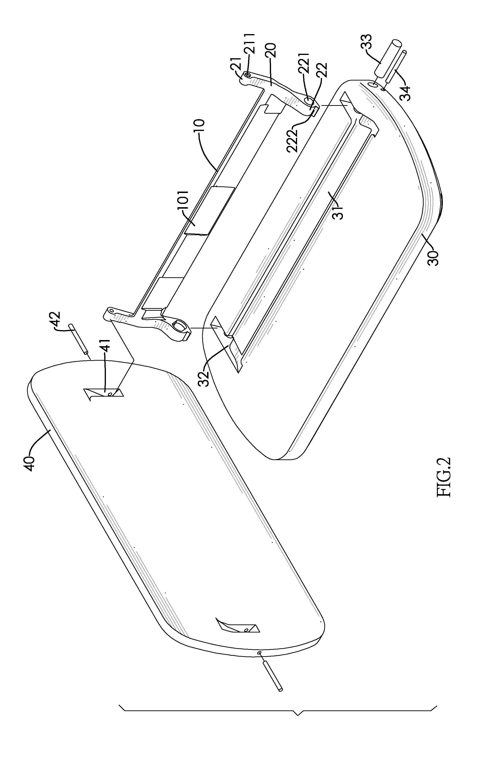
  • Hinge device and electronic device using the same

Examples


first embodiment

[0031]the present invention relates to a hinge device made with a metal injection molding process from an alloy comprising 9 wt % Mn, 16.5 wt % Cr, 9.5 wt % Ni, 3 wt % Si, 0.35 wt % N, 0.2 wt % C, 0.03 wt % S, 0.02 wt % P, 1 wt % Al, 2 wt % Co, 1 wt % Mo, 0.2 wt % O, 0.5 wt % Zr, and Fe that fills up the rest percentage.

[0032]The hinge device of the first embodiment comprises the following features:[0033]Yield strength: 450 MPa.[0034]Tensile strength: 720 MPa.[0035]Elongation percent: 45%.[0036]Hardness: >HRB90.[0037]Saturation induction intensity:

second embodiment

[0038]the present invention relates to a hinge device made with a metal injection molding process from an alloy comprising 10.2 wt % Mn, 21 wt % Cr, 1.2 wt % Ni, 2 wt % Si, 0.85 wt % N, 0.2 wt % C, 0.03 wt % S, 0.2 wt % P, 0.3 wt % Al, 2 wt % Co, 0.8 wt % Ti, 0.5 wt % Cu, 2 wt % W, 3 wt % Mo, 0.1 wt % O, 0.7 wt % Ta, and less than 1 wt % Y and Zr, as well as Fe that fills up the rest percentage.

[0039]The hinge device of the second embodiment comprises the following features:[0040]Yield strength: 620 MPa.[0041]Tensile strength: 790 MPa.[0042]Elongation percent: 25%.[0043]Hardness: >HRC25.[0044]Saturation induction intensity:

third embodiment

[0045]the present invention relates to a hinge device made with a metal injection molding process from an alloy comprising 30 wt % Mn, 25 wt % Cr, 3 wt % Ni, 0.9 wt % N, 0.2 wt % C, 2 wt % Ti, 0.5 wt % Cu, 4 wt % W, 5 wt % Mo, 0.5 wt % B, 1 wt % Nb, 0.6 wt % Ta, and less than 1 wt % Y, La and Zr, as well as Fe that fills up the rest percentage.

[0046]The hinge device of the third embodiment comprises the following features:[0047]Yield strength: 560 MPa.[0048]Tensile strength: 750 MPa.[0049]Elongation percent: 38%.[0050]Hardness: >HRC22.[0051]Saturation induction intensity:

[0052]The forth embodiment of the present invention relates to a hinge device made with a metal injection molding process from an alloy comprising 5 wt % Mn, 30 wt % Cr, 3 wt % Ni, 1.5 wt % Si, 0.4 wt % N, 0.02 wt % C, 0.05 wt % S, 0.03 wt % P, 0.5 wt % Al, 0.5 wt % V, 4 wt % W, 0.8 wt % Nb, 0.6 wt % Ta, and less than 1 wt % La, Ce and Hf, as well as Fe that fills up the rest percentage.

[0053]The hinge device of th...


PUM


Abstract

The hinge in accordance with the present invention is made with a metal injection molding process from an alloy having at least: from 4 to 32 wt % Mn, from 16 to 37 wt % Cr and Fe that fills up the rest percentage.

Description

BACKGROUND OF THE INVENTION[0001]1. Field of the Invention[0002]The present invention relates to a hinge device and to an electronic device using the hinge device. 2. Description of the Prior Art[0003]Terminology[0004]It is well known in the art that elements may be referred to by their names or symbols. The following Table 1 lists names and symbols of elements regarded in the specification and claims of the present invention.TABLE 1NameSymbolManganeseMnChromiumCrNickelNiSiliconSiNitrogenNCarbonCSulfurSPhosphorusPAluminumAlCobaltCoTitaniumTiCopperCuVanadiumVTungstenWMolybdenumMoBoronBOxygenONiobiumNbTantalumTaYttriumYLanthanumLaCeriumCeHafniumHfZirconiumZrIronFe[0005]A conventional mobile electronic device, for example, a notebook computer, a cell phone or a PDA, comprises a base and a screen, as well as a conventional hinge device connecting and enabling the rotating motion of the screen relative to the base. The means for rotating the base and the screen include sliding, folding, ...

Claims


Application Information

Patent Timeline
IPC IPC(8): H05K7/00E05D5/10C22C38/18C22C22/00C22C27/06
CPCC22C22/00C22C27/06C22C30/00C22C30/02Y10T16/557G06F1/1681H04M1/0216H04M1/0237C22C38/38
Inventor LU, YU-CHIHSIEH, YU-CHANLIN, SHUN-TIAN
Owner SHIN ZU SHING
Learn More