
Demineralized cortical bone implants

a cortical bone and bone implant technology, applied in the field of demineralized cortical bone implants, can solve the problems of inability to complete healing, pain and deformities, severe pain and deformities, etc., and achieve the effect of easy differentiation

Inactive Publication Date: 2012-05-10
SPINEOLOGY +1
View PDF4 Cites 18 Cited by
  • Summary
  • Abstract
  • Description
  • Claims
  • Application Information

AI Technical Summary

Benefits of technology

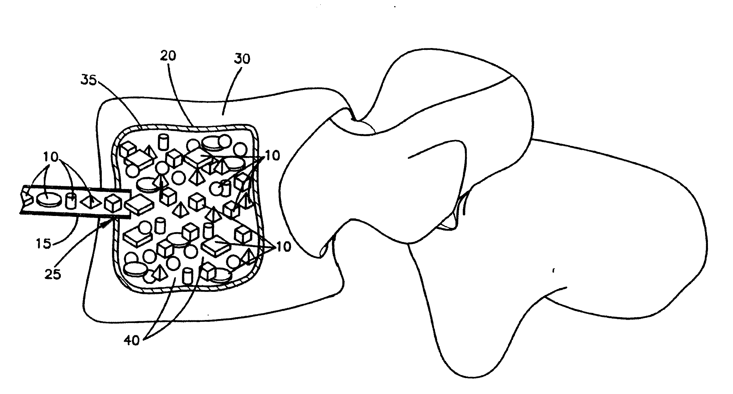
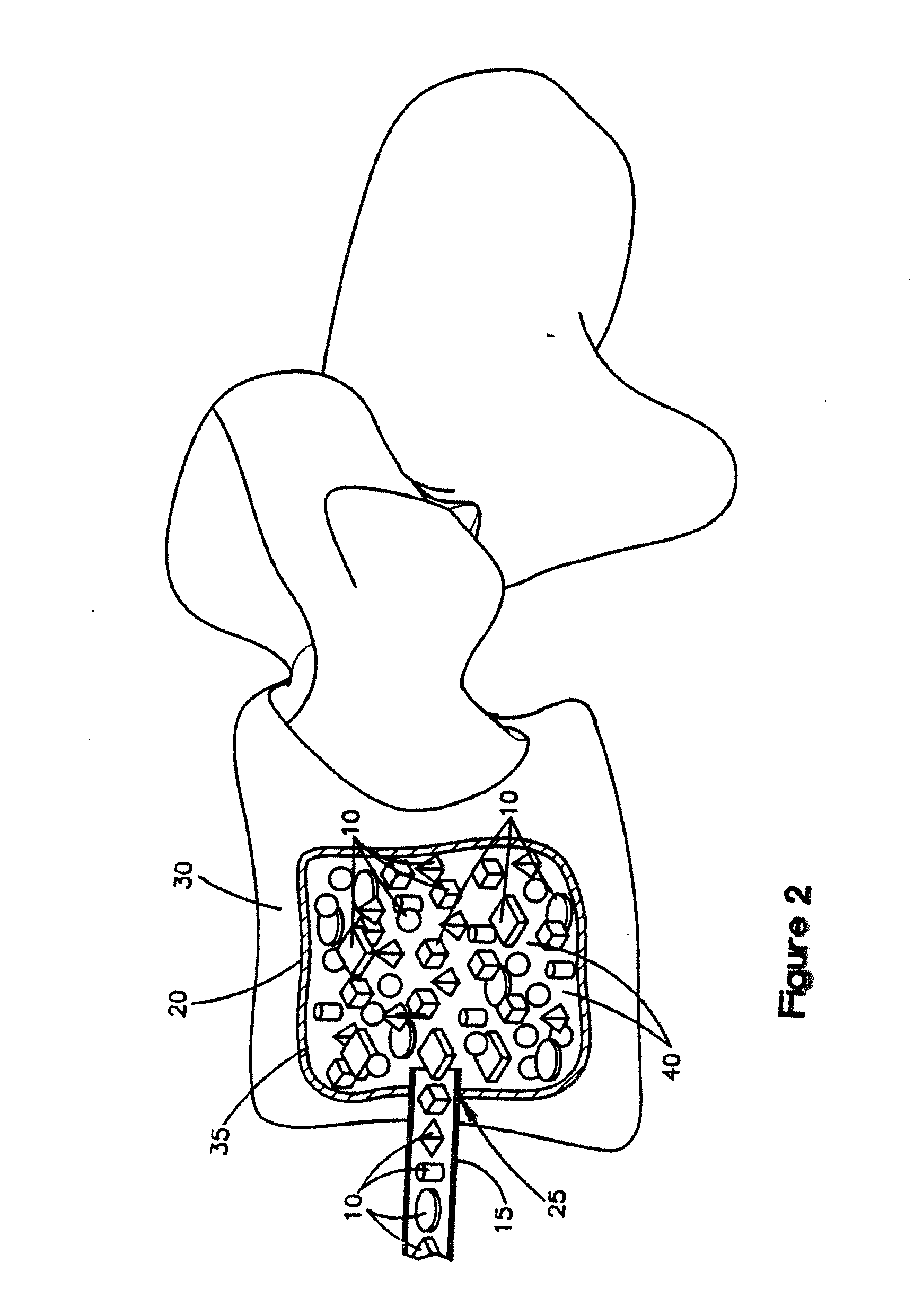
[0022]The implants and methods of treatment described herein provide certain advantages. One advantage is that the implants comprise a plurality of separate cortical bone units, which are harder, firmer, and denser than other materials, such as spongy, cancellous bone or bone powders, which are used in other spinal implants. Thus, the implants described herein are well suited to load bearing applications when inserted inside a cavity. When the implants are used in a spinal application, they may be used to stabilize the surrounding vertebrae after implantation.
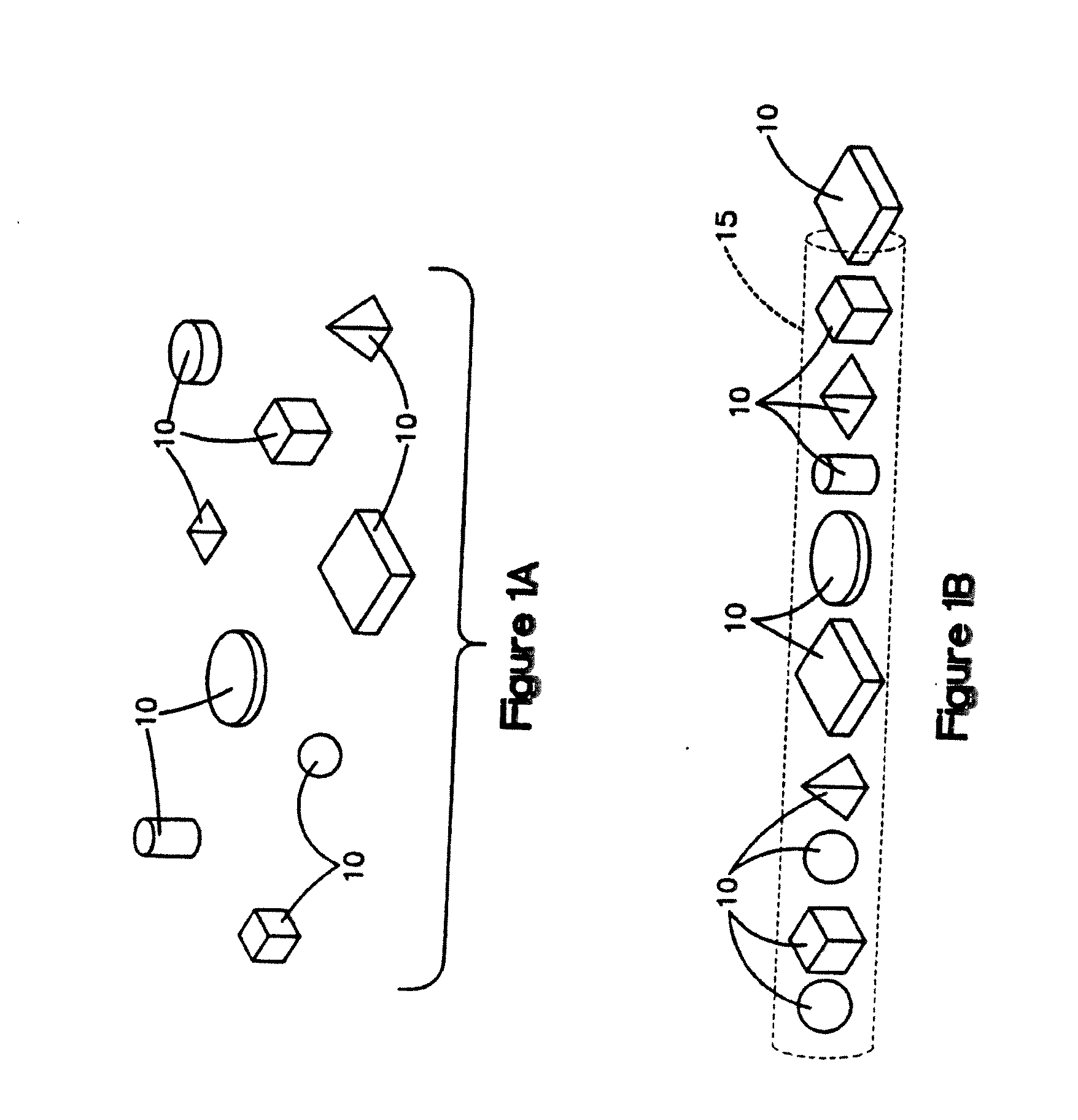
[0024]Furthermore, compared to powdered materials, such as bone powders, for treating spinal conditions, the implants comprising cortical bone units described herein can be easier for surgeons or other medical personnel to insert into a patient during the time of minimally invasive spine surgery through a small diameter cannula. Powdered materials that are used to treat spinal conditions are often placed in tubes or containers. The surgeons or medical personnel deliver the powdered material to the patient by extruding, the powdered material from the tube or container. Because the powdered material has relatively small particle sizes, the material has a tendency to become packed and forms a dense mass in the tube or container. The packing of the powdered material in the tube or container can cause a jam therein that makes it difficult for the surgeon to extrude the powdered material. In contrast, because of the relatively larger size of the cortical bone units described herein, the cortical bone units do not form a dense mass that can jam the tube or container from which they are being delivered. In certain embodiments, the cortical bone units can be delivered from the tube or container in which they are placed, so that they are dispensed in single file from tubes or containers. The size of the cortical bone units may also eliminate the need for a carrier, which may be needed when using powdered material where the carrier is included to create flowability and avoid or reduce the jamming problems that occur when using powdered material.

Problems solved by technology

As the patient's bone weakens, the vertebral bodies lose height and collapse, leading to severe pain and deformity.
Burst and compression fractures of the vertebral bodies also occur in trauma cases, again leading to pain and deformities.
One of the disadvantages of using bone cement is that, once it is injected inside the patient, the bone cement is an inorganic material that acts as a foreign body, and thus, does not allow for complete healing and may instead lead to bone disease.
Moreover, bone cement is typically stiffer than bone, which may increase the incidence of adjacent level fractures in the spine.
Also, bone cement leakage may cause complications, and has been reported to occur in vetebroplasty and kyphoplasty procedures.
If leakage does occur, PMMA bone cements can cause soft tissue injury due to the high temperatures of the exothermic polymerization reaction.
In addition, PMMA forced into the vascular system can cause emboli.
This can cause inflammation or micromotion instability, resulting in pain, and loss of motion.
In addition, certain materials that have been used do not allow bone healing through the entire implant to achieve complete interbody fusion since they may be synthetic materials that do not remodel into bone.
Additionally, while implants have been used for spinal fusion, it has not always been possible to size an implant to fit the implant site.
Moreover, the materials that have been used for vertebral fusion, such as titanium and polyether-etherketone (PEEK), do not always provide the optimal degree of mechanical support.
Also, implant materials that are radiopaque do not allow for newly formed bone to be readily detected during follow-up x-rays.

Method used


Image

  • Demineralized cortical bone implants
  • Demineralized cortical bone implants
  • Demineralized cortical bone implants

Examples


example 1

Preparation of Demineralized Cortical Bone Units

[0103]Fully demineralized cortical bone units were processed by cutting a long bone shaft into 2.4 mm thick cortical rings using a band saw. Lipids were then removed from the cortical rings using Tween 80 solution, cleaned using hydrogen peroxide, and then demineralized with an extended soak using 0.6N HCl to reach a residual calcium level below 0.5 wt %. The demineralized cortical rings were then cut into cubes with 2.4 mm sides. Afterwards, the pH was restored to physiological levels using a buffered salt solution. The demineralized cortical bone units was then soaked in ethanol, rinsed with water, and then lyophilized to a residual moisture content of less than 6 wt %.

example 2

Comparative Example—Preparation of a Composition of Non-Demineralized Corticocancellous Bone Granules, Demineralized Cortical Bone Powder and Sodium Hyaluronate

[0104]A mixture containing non-demineralized corticocancellous bone granules, demineralized cortical bone powder and sodium hyaluronate was produced as follows. Pieces of cortical and cancellous bone were cut into smaller pieces and delipidized using a surfactant solution. Subsequently, the cortical bone pieces and then the cancellous bone pieces were separately milled into granules with a size range of 212 μm to 850 μm. The cortical bone granules were then divided into two portions. The first portion was combined with cancellous granules in an 80:20 cortical to cancellous ratio by weight and then further cleaned with peroxide and ethanol. Following this step, the non-demineralized corticocancellous granules were lyophilized to a residual moisture content of less than 6 wt %. The second portion of cortical bone granules was u...

example 3

Comparative Packing Densities Required to Sustain Loads in Confined Compression

[0105]Sustained loading testing was performed to determine the comparative material packing or bulk densities of (1) the demineralized cortical bone units prepared as described in Example 1 above (“the test samples”), and (2) the composition prepared as described in Example 2 above (“the control samples”), which was a mixture of non-demineralized corticocancellous granules, DBM and sodium hyaluronate. A Bionix 858 Test System (MTS, Minneapolis, Minn.) was used to determine the packing densities.

[0106]For the test samples, aliquots of the lyophilized demineralized cortical bone units of Example 1 (0.6 g dry weight each) were re-hydrated in excess saline and then loaded into a porous confined compression chamber. The demineralized cortical bone units were in the shaped of cubes, in which each side was about 2.4 mm. The chamber was 12.5 mm in diameter and contained equally spaced 1 mm pores around its circum...


PUM

PropertyMeasurementUnit
packing densityaaaaaaaaaa

Abstract

Implants comprising a plurality of separate cortical bone units, which have been at least partially demineralized and are osteoinductive, are described herein. The implants can be used in methods for treating bone. Also, disclosed are methods for treating spinal conditions using these implants. The spinal conditions include but are not limited to repairing damage to or defects in the spine, such as fractures in a vertebral body or degeneration of spinal discs.

Description

FIELD OF THE INVENTION[0001]Implants comprising a plurality of separate cortical bone units, which have been at least partially demineralized and are osteoinductive, are described herein. The implants can be used in methods for treating bone. Also disclosed are methods for treating spinal conditions using these implants. The spinal conditions include but are not limited to repairing damage to or defects in the spine, such as fractures in a vertebral body of a patient or degeneration of a spinal disc in a patient.BACKGROUND[0002]Fractures, such as compression or burst fractures, in the vertebral bodies of the spine are common in elderly patients who suffer from osteoporosis. There are approximately 700,000 cases of pathologic vertebral body compression fractures reported annually in the United States. As the patient's bone weakens, the vertebral bodies lose height and collapse, leading to severe pain and deformity. Burst and compression fractures of the vertebral bodies also occur in...

Claims


Application Information

Patent Timeline
Patent Type & Authority Applications(United States)
IPC IPC(8): A61F2/44A61F2/28
CPCA61B17/7095A61L2300/44A61F2/28A61F2/441A61F2/4601A61F2002/2817A61F2002/2839A61F2002/30057A61F2002/30062A61F2002/30224A61F2002/30242A61F2002/30252A61F2002/30253A61F2002/30261A61F2002/30273A61F2002/30588A61F2002/30677A61F2002/444A61F2002/4635A61F2002/4646A61F2002/4649A61F2310/00976A61L27/3608A61L27/3658A61L27/3683A61L27/48A61L27/54A61F2/0063
Inventor SEMLER, ERIC J.BOYLAN, CLINTROCHE, KAREN
Owner SPINEOLOGY
Learn More