Method for manufacturing base tire, curing machine, and base tire
a technology of base tires and curing machines, applied in the field of curing, can solve the problems of tire wear on the tread surface, tire life end, tire use on vehicles, etc., and achieve the effects of uniform hardness, small rotational resistance, and uniform cure degr
- Summary
- Abstract
- Description
- Claims
- Application Information
AI Technical Summary
Benefits of technology
Problems solved by technology
Method used
Image

Examples
first embodiment
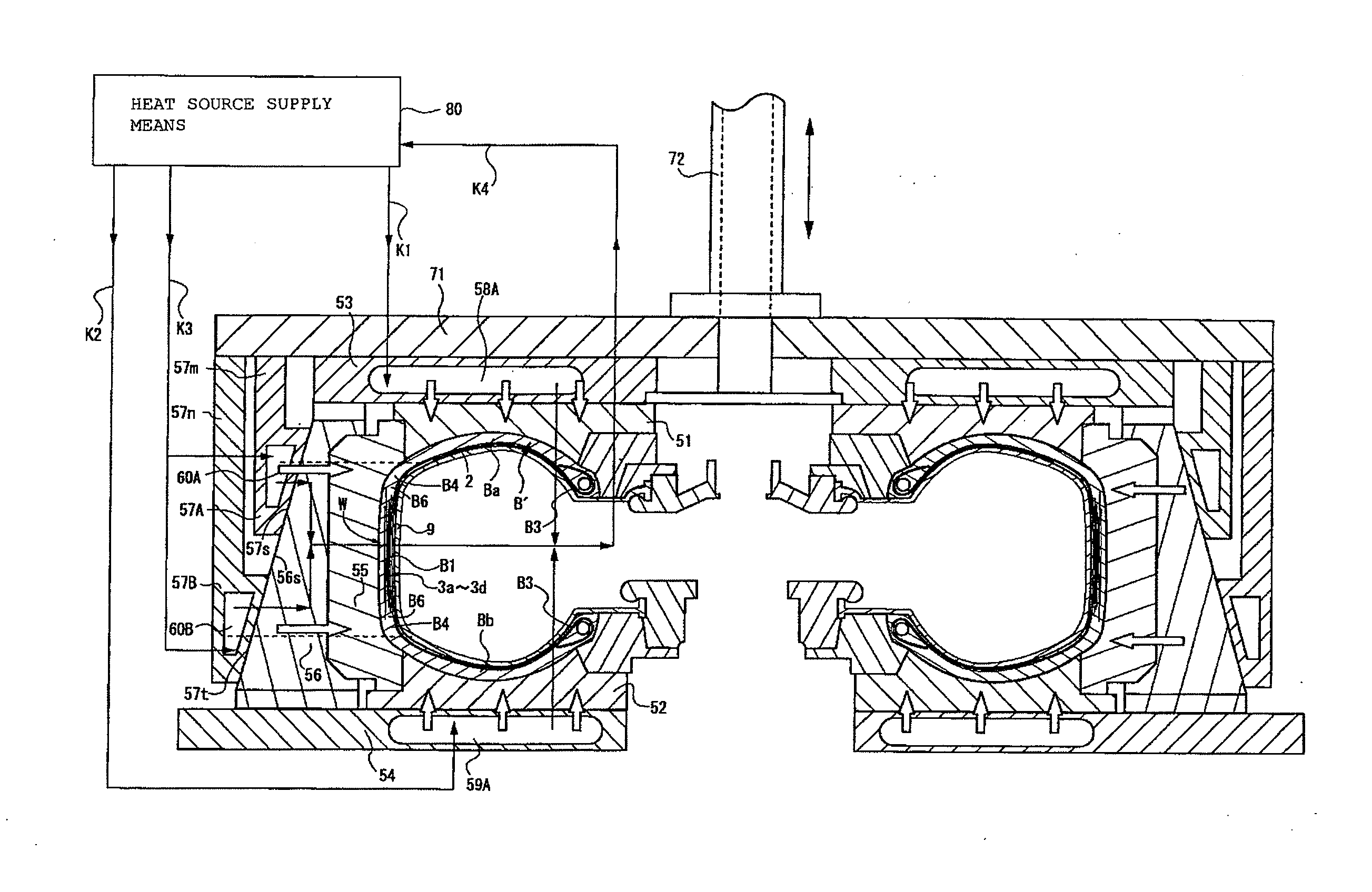
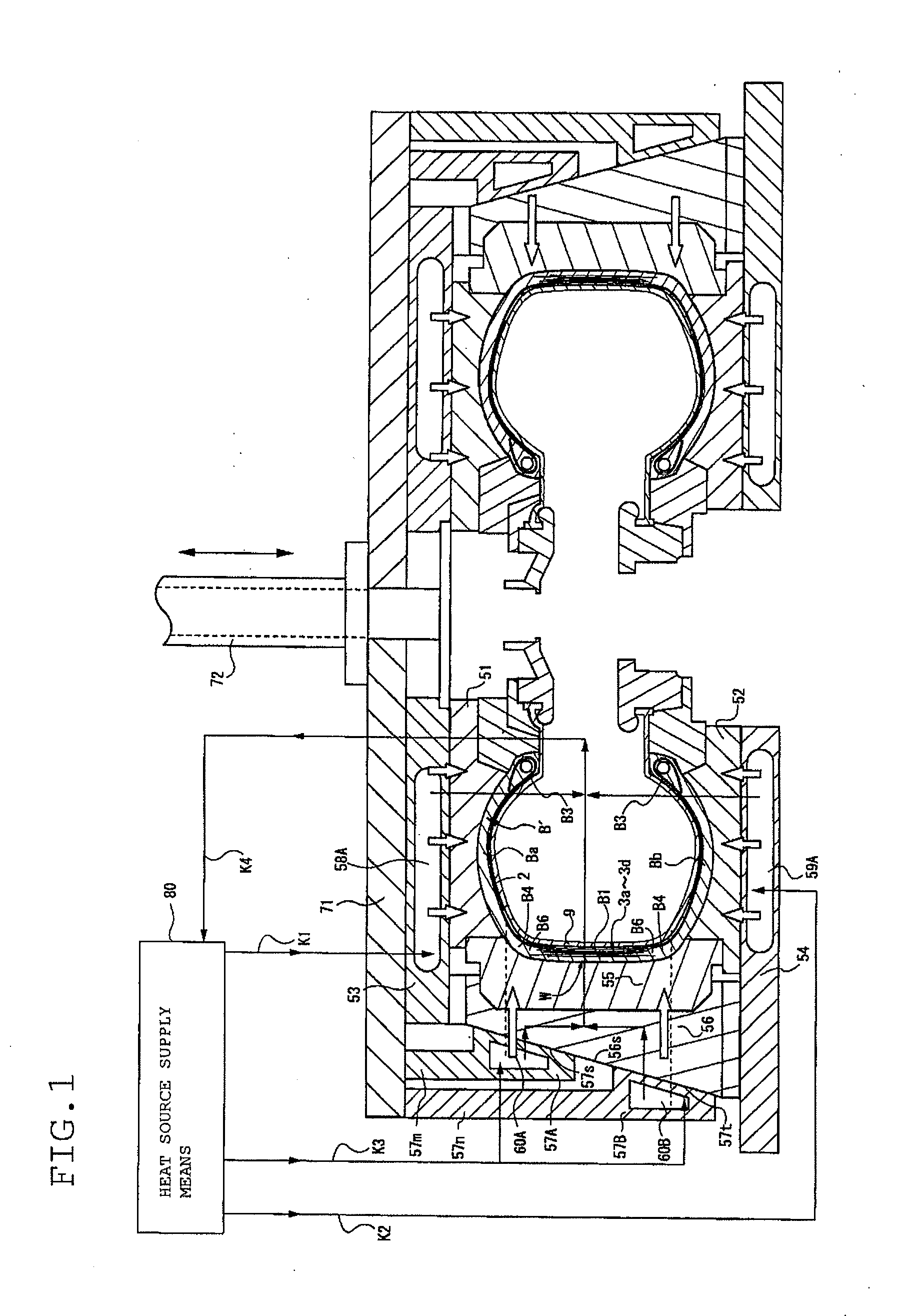
[0056]FIG. 1 shows a curing machine of a base tire according to a preferred embodiment of the present invention. Note that, in the figure, identical components, which are also found on the conventional curing machine, are given identical reference numerals and the repeated description thereof will be omitted as appropriate.
[0057]In FIG. 1, the reference numerals 51 and 52 denote an upper mold and a lower mold, which have each a ringed disk shape. The upper mold 51 is movable up and down relative to the lower mold 52. The upper mold 51 and the lower mold 52, in contact with the side regions Ba and Bb which are the sides of a green tire B′ to be cured, not only cure the side regions Ba and Bb, but also emboss the tire size, serial number, and the like on the side surfaces of the base tire. The upper mold 51 and the lower mold 52 are respectively mounted to an upper platen 53 and a lower platen 54, which serve as a first heating means. Formed inside the upper platen 53 and the lower pl...
second embodiment
[0082]In the first embodiment, it has been described that the outer rings 57A and 57B as the second heating means consist of a plurality of (two) divisions, and the steam pathways 60A and 60B are formed independently inside the outer rings 57A and 57B, respectively. However, the steam pathways 60A and 60B may be formed separately within a single outer ring 57, spaced apart from each other in the axial direction in the tread region.
[0083]For example, as shown in FIG. 3, the steam pathway 60A may be formed in a position facing the shoulder portion B4 on the upper mold 51 side, and the steam pathway 60B in a position facing the shoulder portion B4 on the lower mold 52 side, within the outer ring 57 as the second heating means.
[0084]In other words, the upper platen 53 and the lower platen 54 are structured as the upper and lower heating sections serving as the first heating means for heating the upper and lower sides of the green tire B′. The outer ring 57 is structured as the shoulder ...
third embodiment
[0085]In the second embodiment, it has been described that two independent steam pathways 60A and 60B are formed inside a single outer ring 57 as the second heating means, spaced apart from each other in the axial direction along the tread region. However, as shown in FIG. 4, three independent heating sections may be provided by adding a steam pathway 60C as the middle heating section between the steam pathways 60A and 60B.
[0086]In this structure, the arrangement for supply of steam is such that the steam pathways 58A and 59A in the upper and lower platens 53 and 54 as the first heating means in the side regions Ba, Bb and the steam pathways 60A, 60B, and 60C in the outer ring 57 as the second heating means are individually connected to the heat source supply means 80 supplying steam as the heating medium. And a valve 61, as an operation unit enabling the control of the amount of heating, is provided between the steam pathway 60C as the middle heating section and the heat source sup...
PUM
| Property | Measurement | Unit |
|---|---|---|
| Temperature | aaaaa | aaaaa |
| Electrical conductor | aaaaa | aaaaa |
| Heat | aaaaa | aaaaa |
Abstract
Description
Claims
Application Information
 - R&D
- Intellectual Property
- Life Sciences
- Materials
- Tech Scout
- Unparalleled Data Quality
- Higher Quality Content
- 60% Fewer Hallucinations
Browse by: Latest US Patents, China's latest patents, Technical Efficacy Thesaurus, Application Domain, Technology Topic, Popular Technical Reports.
© 2025 PatSnap. All rights reserved.Legal|Privacy policy|Modern Slavery Act Transparency Statement|Sitemap|About US| Contact US: help@patsnap.com