
Pipeline assembly comprising an anchoring device

a technology of pipeline and anchoring device, which is applied in the direction of pipe laying and repair, waterborne vessels, mechanical devices, etc., can solve the problems of pipeline fatigue, movement and rotation of the target device, loss in lifetime, etc., and achieve the effect of reducing pipeline movemen

Inactive Publication Date: 2012-05-03
HEEREMA MARINE CONTRACTORS NEDERLAND
View PDF3 Cites 13 Cited by
  • Summary
  • Abstract
  • Description
  • Claims
  • Application Information

AI Technical Summary

Benefits of technology

[0027]The connecting device limits the freedom of movement of the coupling point, thereby substantially reducing movements in the touch-down zone of the pipeline. Hence, fatigue of the pipeline, in particular in the touch-down zone, is substantially decreased.
[0099]The required form and position of the pipeline can be achieved by simply maneuvering the delivery end by the pipeline laying vessel. Hence, no complicated operations at the seabed are necessary.

Problems solved by technology

Every movement of the riser causes an increased fatigue of the pipeline and thus, a loss in lifetime.
A target device located at the water level is generally subject to forces from wind, waves and water currents, which cause movements and rotations of the target device.
If a delivery end of the riser is connected with the target device, the delivery end moves together with the target device, and the movements and rotations of the target device cause fatigue in the riser.
This is generally disadvantageous.
Installing a long anchoring line is generally difficult.
Supporting the delivery end of the riser with a buoyancy device does not prevent all movements of the pipeline.
These forces may still cause movements of at least a part of the riser, thereby causing fatigue.
This causes an increased fatigue in the touch-down zone.
Apart from an increased fatigue, a movement of the touch-down zone results in a risk of the seabed section of the pipeline being damaged, for instance due to wear and tear from the pipe-soil interaction.
The device of U.S. Pat. No. 4,023,517 has a grave disadvantage in that extensive construction work is necessary at the seabed in order to install the flexible hose and connect it to both the horizontal pipeline and the vertical riser.
The device of U.S. Pat. No. 4,023,517 also extends above the water surface, thereby being influenced by forces from wind and waves, which seriously increase fatigue of the riser.
The movement induces strong fatigue in the riser, leading to a short lifetime.
The riser system of U.S. Pat. No. 4,802,431 extends above the water surface, and is thus influenced by forces from wind and waves, which further increases the fatigue of the riser.
The combination of a lazy wave form and a direct connection to a platform at the water surface creates large, varying loads on the riser system, leading to strong fatigue and a short lifetime.
Such a flexible pipeline is only suitable for smaller water depths.
This configuration leads to a strong fatigue of the pipeline, because large dynamic loads may be exerted on the pipeline.

Method used


Image

  • Pipeline assembly comprising an anchoring device
  • Pipeline assembly comprising an anchoring device
  • Pipeline assembly comprising an anchoring device

Examples


Embodiment Construction

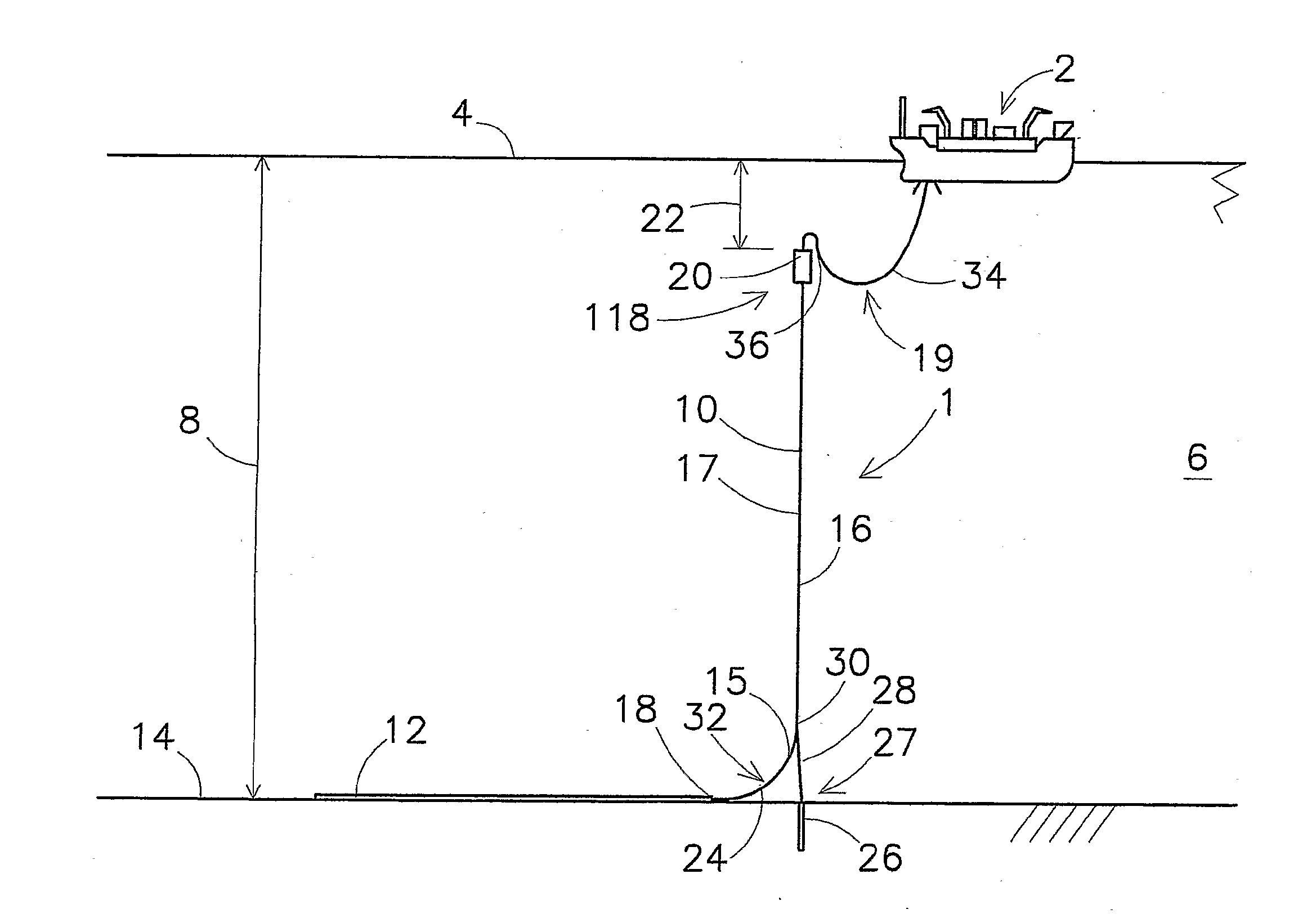
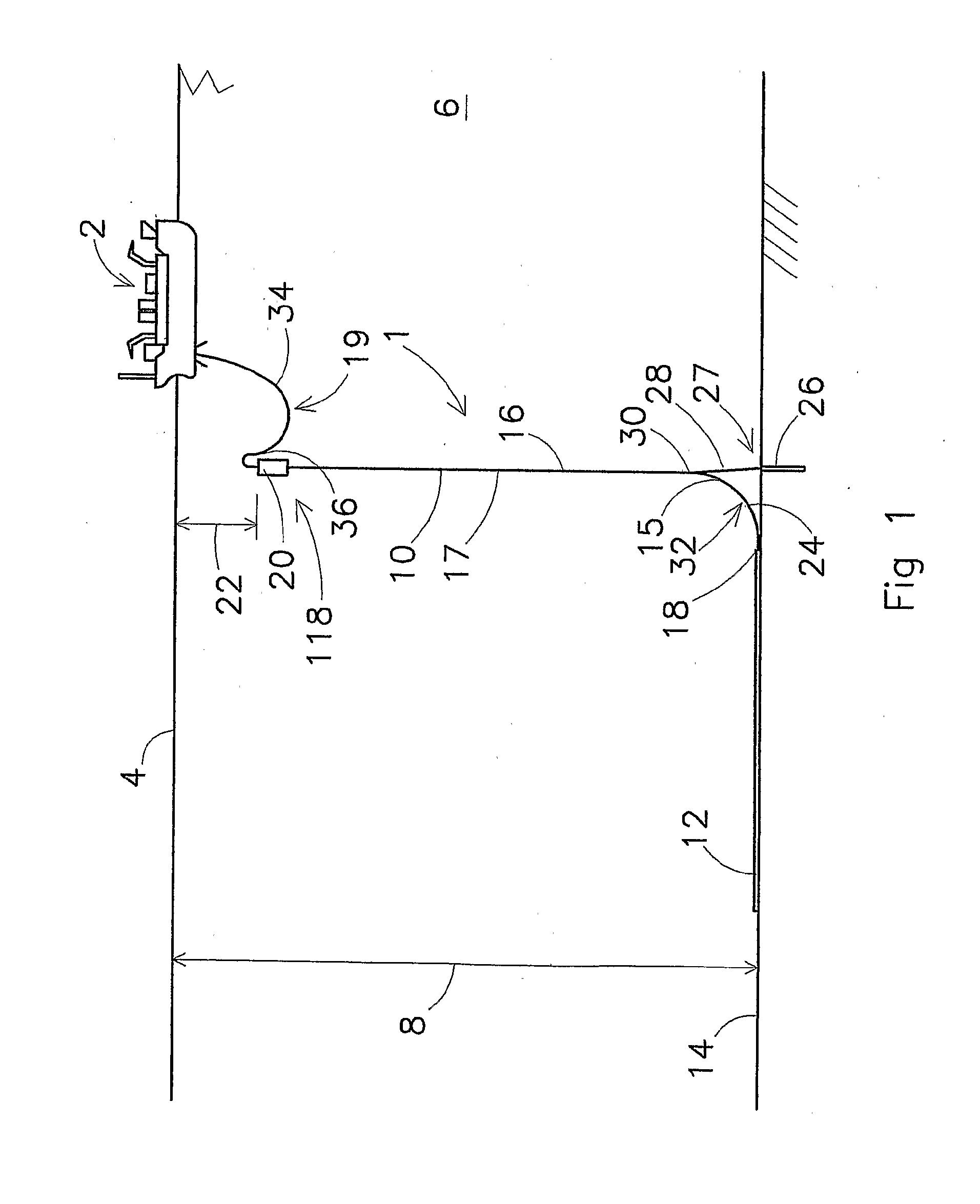
[0139]FIG. 1 shows an embodiment of a pipeline assembly 1 according to the invention. A target device 2 is shown, positioned at a water surface 4. The target device 2 may be an FPSO, or a different kind of vessel. The water 6 may have a substantial depth 8, for instance ranging between one and three kilometres.

[0140]A pipeline 10 comprises a seabed section 12, which rests on a seabed 14, and a riser section 16, which extends from a touchdown point 18 at the seabed 14 to a buoyancy device 20, positioned at a depth 22 under the water surface 4. The buoyancy device 20 exerts an upward force on the pipeline 10. The depth 22 is chosen such, that the buoyancy device 20 is substantially free of forces of waves and wind. At least one flexible pipeline 34 connects a delivery end 36 of the pipeline 10 to the target device 2 for providing a fluid connection between the delivery end 36 and the target device 2. The seabed section 14 may be connected at one end thereof to an oil well (not shown)....


PUM


Abstract

The invention relates to a pipeline assembly and a method of installing a pipeline assembly, wherein the pipeline extends at least in part on a seabed and curves upwardly from the seabed along a curved section thereof, the pipeline extending toward a delivery end provided at the water surface, wherein a connecting device connects the pipeline at a coupling point to an anchoring device at the seabed for preventing the coupling point from moving upward. The invention further relates to a pipeline device comprising at least two pipeline assemblies which are interconnected at a substantial distance from the seabed.

Description

CROSS-REFERENCE TO RELATED APPLICATIONS[0001]This application is a continuation of U.S. patent application Ser. No. 12 / 089,437, filed May 5, 2008, which claims the benefit of the National Stage of International Application No. PCT / NL2006 / 000507, filed Oct. 9, 2006, which in a continuation-in-part of U.S. application Ser. No. 11 / 245,477, filed Oct. 7, 2005, the contents of which is incorporated by reference herein.FIELD OF THE INVENTION[0002]The present invention relates to a pipeline assembly. The present invention further relates to a method for installing the pipeline assembly.DESCRIPTION OF THE PRIOR ART[0003]Pipelines are widely applied in the off-shore industry, for instance for conveying a fluid or a mixture of fluids from an oil well on a seabed to a target device located at a water surface. This target device may be a vessel or a platform, for instance a floating production and storage platform, generally known as an FPSO.[0004]Often, a pipeline is laid which rests on a seab...

Claims


Application Information

Patent Timeline
Patent Type & Authority Applications(United States)
IPC IPC(8): F16L1/12
CPCB63B27/24E21B17/012E21B17/015E21B17/017F16L1/18F16L1/19F16L1/20
Inventor WOLBERS, DIRK RIENTSCOPPENS, TON
Owner HEEREMA MARINE CONTRACTORS NEDERLAND
Learn More