
Method for measuring and/or calibrating a gas sensor

a gas sensor and sensor technology, applied in the direction of instruments, machines/engines, electrochemical variables, etc., can solve the problems of affecting the accuracy of measurement, etc., to achieve the effect of improving the measurement accuracy and being readily uploaded and used

Inactive Publication Date: 2012-04-26
ROBERT BOSCH GMBH
View PDF4 Cites 36 Cited by
  • Summary
  • Abstract
  • Description
  • Claims
  • Application Information

AI Technical Summary

Benefits of technology

The present invention provides a method for in-situ measurement and calibration of a gas sensor, particularly for determining oxygen and nitrogen oxides in exhaust gases of internal combustion engines. The method involves removing oxygen and other gas components from the sensor using electrochemical pumping processes, and then introducing oxygen in a controlled manner using a pump voltage or current. The changes caused by the introduced oxygen are measured and used to calibrate the sensor. This method allows for accurate and efficient calibration of the sensor while it is in operation, and can detect and compensate for changes in sensor properties over time.

Problems solved by technology

However, detecting nitrogen oxides is not an easy task due to the high amount of oxygen also being present in the exhaust gas.
In particular, leakage currents at the sensor itself, at the sensor housing or in the cable may be erroneously interpreted as an NOx current.
Over the lifetime of the sensor, however, shifts may develop, which falsify the basis value of the NOx signal and its gradient, due to various aging phenomena such as change in the internal resistance, electrode aging, temperature drift, change in the contacts / insulation resistances, etc.
Furthermore, an increased burst of oxygen to the decomposition electrode may result in a change in the NOx signal.
If this burst has not already occurred during the starting calibration, the burst will cause significant measuring errors during ongoing operation.
This is, however, difficult because there is no independent measurement of the NOx value which might be used for calibration.

Method used


Image

  • Method for measuring and/or calibrating a gas sensor
  • Method for measuring and/or calibrating a gas sensor
  • Method for measuring and/or calibrating a gas sensor

Examples


Embodiment Construction

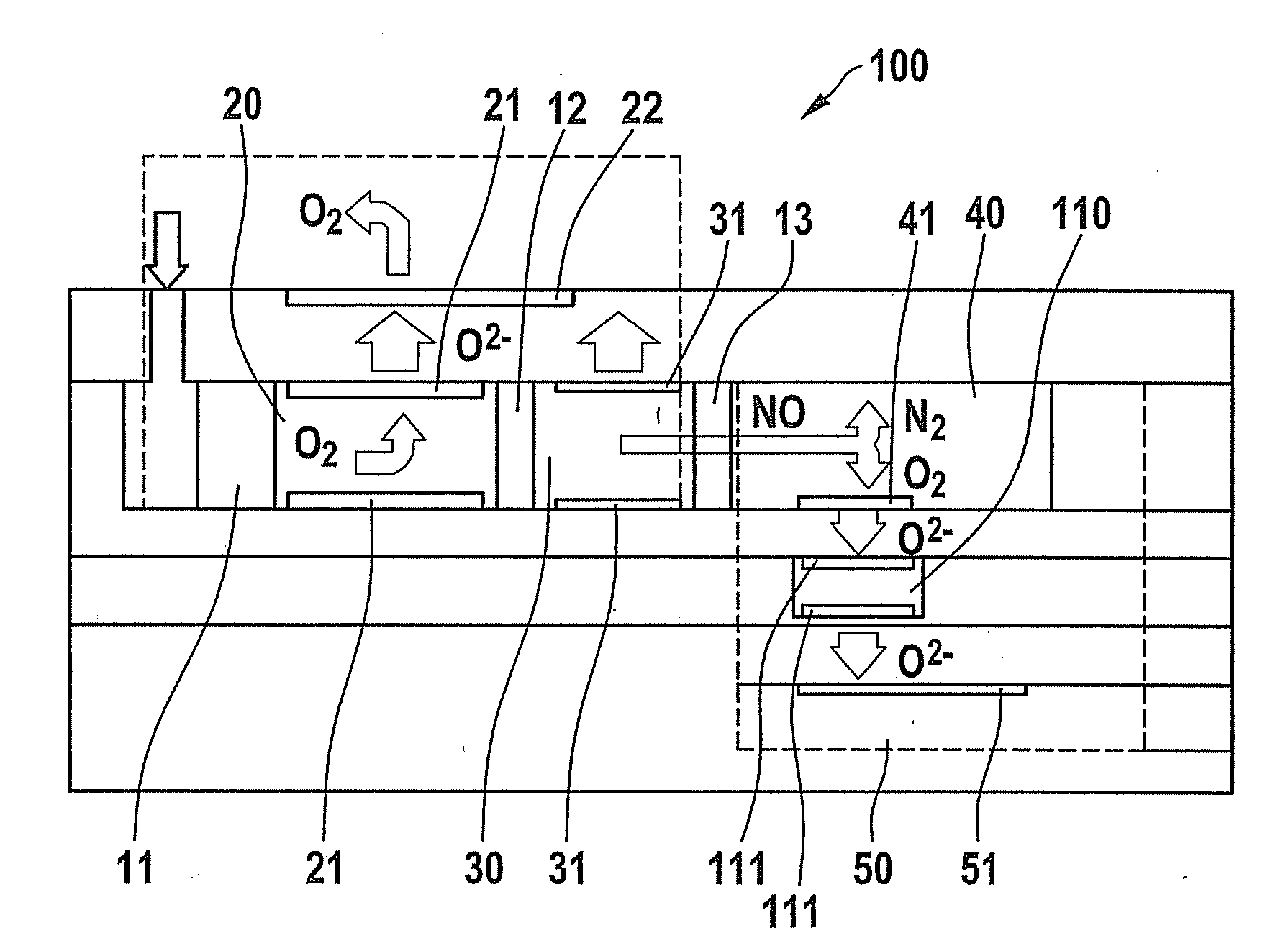
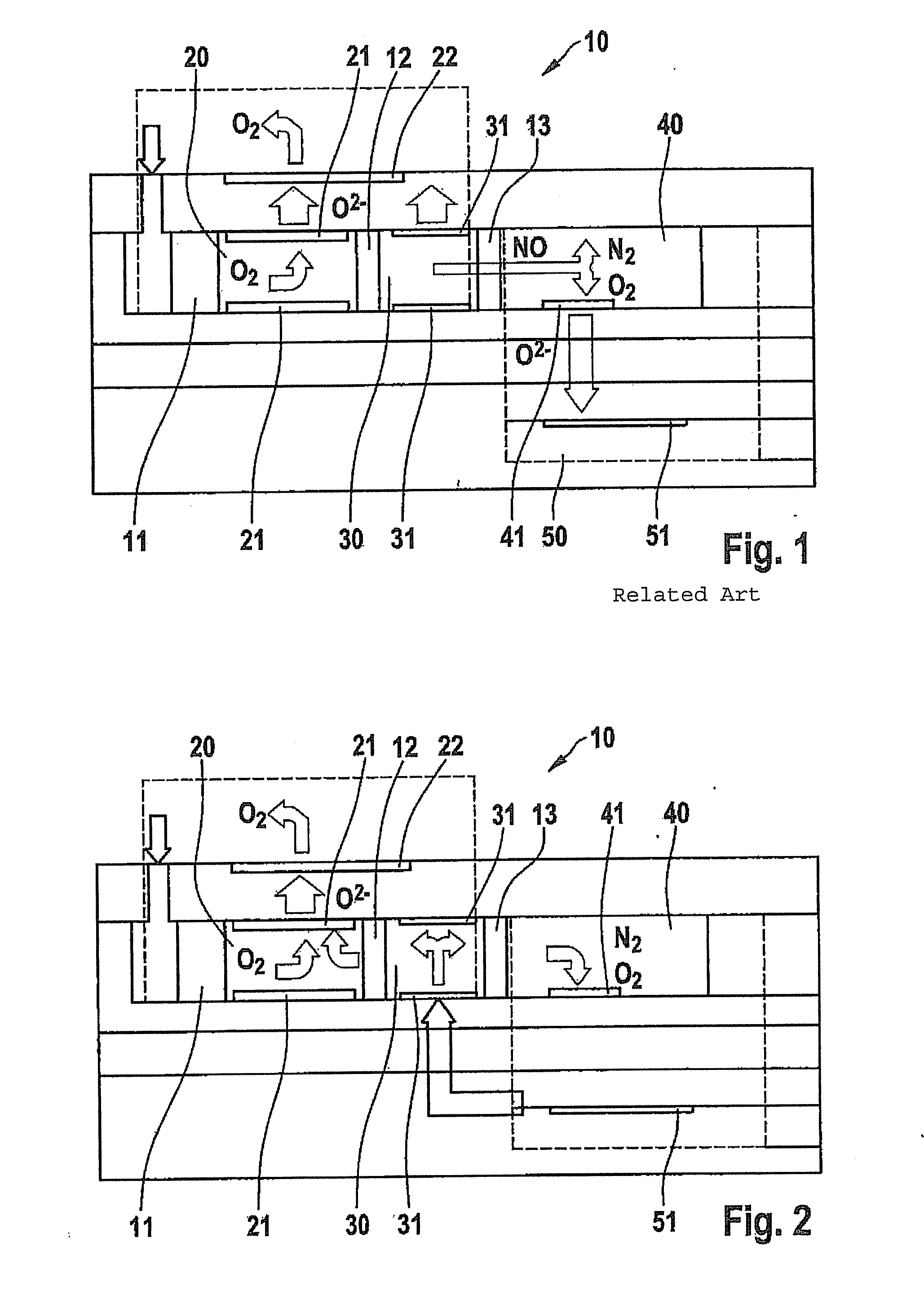
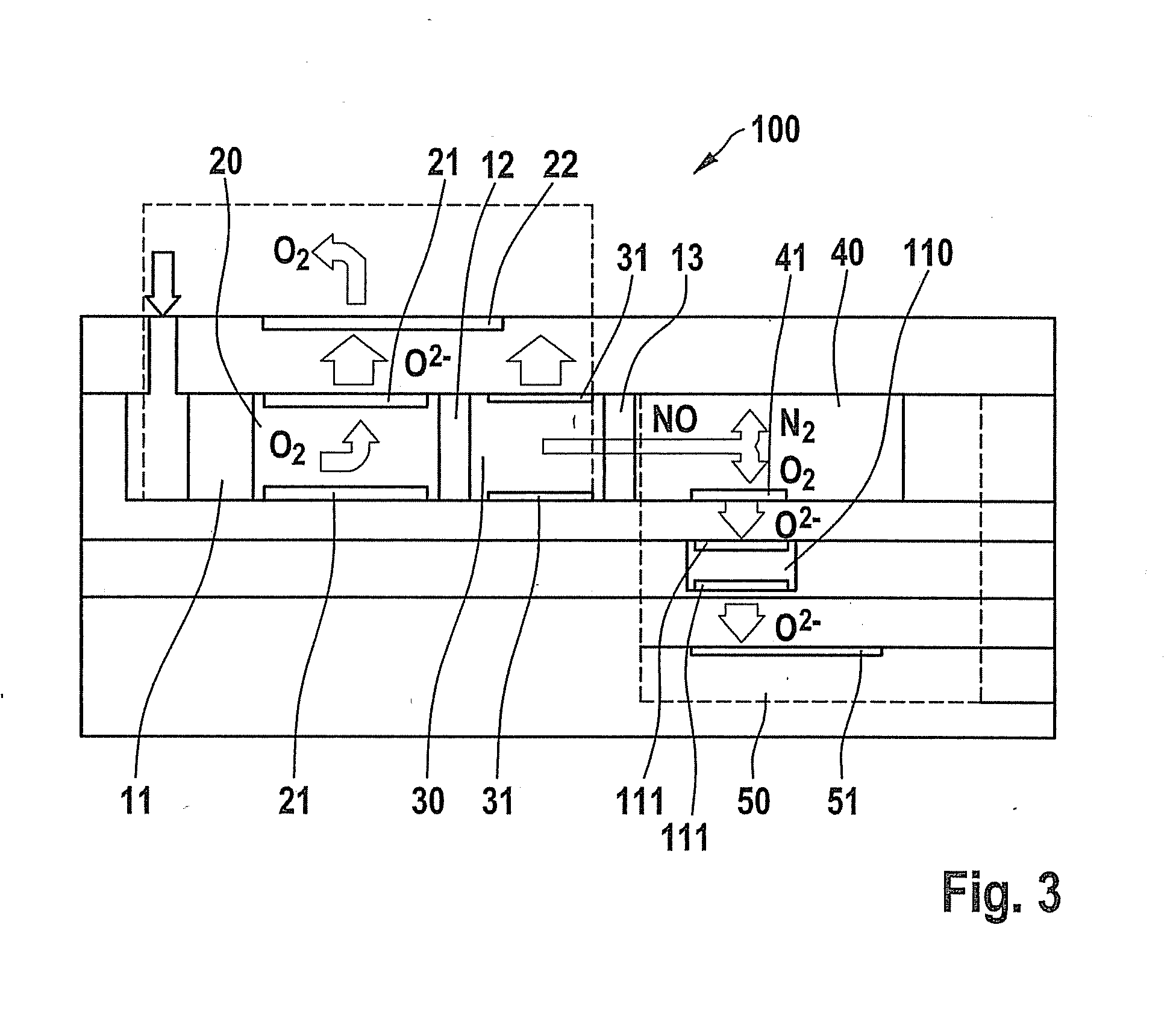
[0023]The operation of a conventional double chamber nitrogen oxide sensor is illustrated in the following based on FIG. 1. Nitrogen oxide sensor 10 includes a first chamber 20 having a first internal pump electrode pair (IPE1) 21. In a second chamber 30, another internal pump electrode pair (IPE2) 31 is provided. In a third chamber 40, an NOx electrode 41 is situated as a decomposition electrode provided for decomposing the nitrogen oxides. An external pump electrode (APE) 22 is situated facing the exhaust gas. A reference electrode (RE) 51 is provided in an air reference channel 50 or a pumped reference cell. During a normal conventional operation, the exhaust gas mixture enters chamber 20 of the sensor in this diagram from above on the left side of sensor 10 through a first diffusion barrier 11. A voltage between first internal pump electrode 21 and external pump electrode 22 or also reference electrode 51 is used to remove the oxygen from the exhaust gas mixture. Furthermore, se...


PUM

PropertyMeasurementUnit
voltageaaaaaaaaaa
voltageaaaaaaaaaa
voltageaaaaaaaaaa

Abstract

A method for measuring and / or calibrating a gas sensor for determining oxygenic gas components in gas mixtures in exhaust gases of internal combustion engines. The gas sensor has one internal pump electrode IPE, one external pump electrode APE and one decomposition electrode NOE. The measurement and / or calibration may be carried out during the ongoing operation of the gas sensor by removing the gas component and / or oxygen from one of the chambers, by introducing oxygen in a controlled manner into one of the chambers with the aid of electrochemical pumping processes. The changes caused by the introduced oxygen are measured against an additional electrode and the gas sensor may be measured and / or calibrated using the measured values.

Description

CROSS REFERENCE[0001]The present application claims the benefit under 35 U.S.C. §119 of German Patent Application No. DE 102010042701.2 filed on Oct. 20, 2010, which is expressly incorporated herein by reference in its entirety.FIELD OF THE INVENTION[0002]The present invention relates to a method for measuring and / or calibrating a gas sensor provided for determining, in particular, oxygenic gas components in gas mixtures.BACKGROUND INFORMATION[0003]Due to environmental consciousness, which has increasingly grown in the past few years, and thanks to various technical developments, it was possible to significantly reduce the amount of harmful substances in the exhaust gases of internal combustion engines. Nitrogen oxides (NO, NO2, in general NOx), a significant part of which may be reduced to nitrogen during an after-treatment of exhaust gases, for example with the aid of selective catalytic reduction, continue to be an important emission class. In order to be able to analyze and opti...

Claims


Application Information

Patent Timeline
Patent Type & Authority Applications(United States)
IPC IPC(8): G01N27/403
CPCG01N27/4175G01N27/4074F01N3/208F01N2560/026F01N2610/02Y02T10/12
Inventor CLASSEN, THOMAS
Owner ROBERT BOSCH GMBH
Learn More