Work machine and control method for work machines

a work machine and control method technology, applied in the direction of fluid couplings, servomotors, couplings, etc., can solve the problems of loss of hydraulic pressure, inability to reduce the opening size of the control valve for the non-prioritized actuator, and shorten the flow rate of hydraulic fluid, so as to inhibit the opening area of the first direction switch valve and inhibit the action speed of the actuator

Active Publication Date: 2012-04-19
KOMATSU LTD
View PDF18 Cites 5 Cited by
  • Summary
  • Abstract
  • Description
  • Claims
  • Application Information

AI Technical Summary

Benefits of technology

[0005]In the well-known work machines, however, the opening size of the control valve for the non-prioritized actuator is reduced only based on an operation of an operating unit for instructing actions of the actuators. Even if a large load is herein applied to the non-prioritized actuator, the opening size of the control valve is reduced when a predetermined operation is executed for the operating unit. Therefore, the action speed of the actuator may be reduced. Further, when a large load is applied to the non-prioritized actuator, the hydraulic fluid easily flows towards the prioritized actuator. Therefore, a sufficient flow rate of the hydraulic fluid can be supplied to the prioritized actuator without reducing the opening size of the control valve for the non-prioritized actuator. Nevertheless, it is unavoidable to reduce the opening size of the control valve for the non-prioritized actuator. This causes loss of the hydraulic pressure.
[0006]It is an object of the present invention to provide a work machine and a control method thereof for inhibiting slowdown of the action speed of an actuator and occurrence of hydraulic pressure loss in executing a combined operation.
[0014]According to the work machine of the first aspect of the present invention, the opening area of the first direction switch valve in executing the combined operation is controlled to be less than or equal to that in executing the single operation. The magnitude of the opening area is herein determined based on the hydraulic pressure detected by the first hydraulic pressure detector unit. Therefore, it is possible to determine the opening area of the first direction switch valve in accordance with an actual load of the first actuator. It is thereby possible to inhibit the opening area of the first direction switch valve from being unnecessarily constricted. As a result, it is possible to inhibit slowdown of the action speed of the actuator in executing the combined operation and occurrence of hydraulic pressure loss.
[0020]According to the method of controlling a work machine of the seventh aspect of the present invention, the opening area of the first direction switch valve in executing the combined operation is controlled to be less than or equal to that in executing the single operation. The magnitude of the opening area is herein determined based on the hydraulic pressure detected by the first hydraulic pressure detector unit. Therefore, it is possible to determine the opening area of the first direction switch valve in accordance with actual load acting on the first actuator. In other words, it is possible to inhibit the opening area of the first direction switch valve from being unnecessarily constricted. It is consequently possible to inhibit slowdown of the action speed of the actuator in executing the combined operation and occurrence of hydraulic pressure loss.

Problems solved by technology

In this case, shortage of the flow rate of the hydraulic fluid is problematic in a more loaded actuator.
Further, when a large load is applied to the non-prioritized actuator, the hydraulic fluid easily flows towards the prioritized actuator.
Nevertheless, it is unavoidable to reduce the opening size of the control valve for the non-prioritized actuator.
This causes loss of the hydraulic pressure.
However, occurrence of such hunting can be herein inhibited by using the fixed value as the hydraulic pressure to be supplied to the second actuator.

Method used


Image

  • Work machine and control method for work machines
  • Work machine and control method for work machines
  • Work machine and control method for work machines

Examples


Embodiment Construction

External Structure

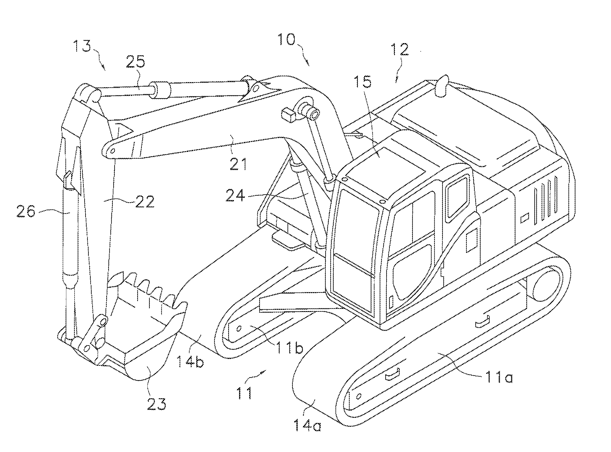
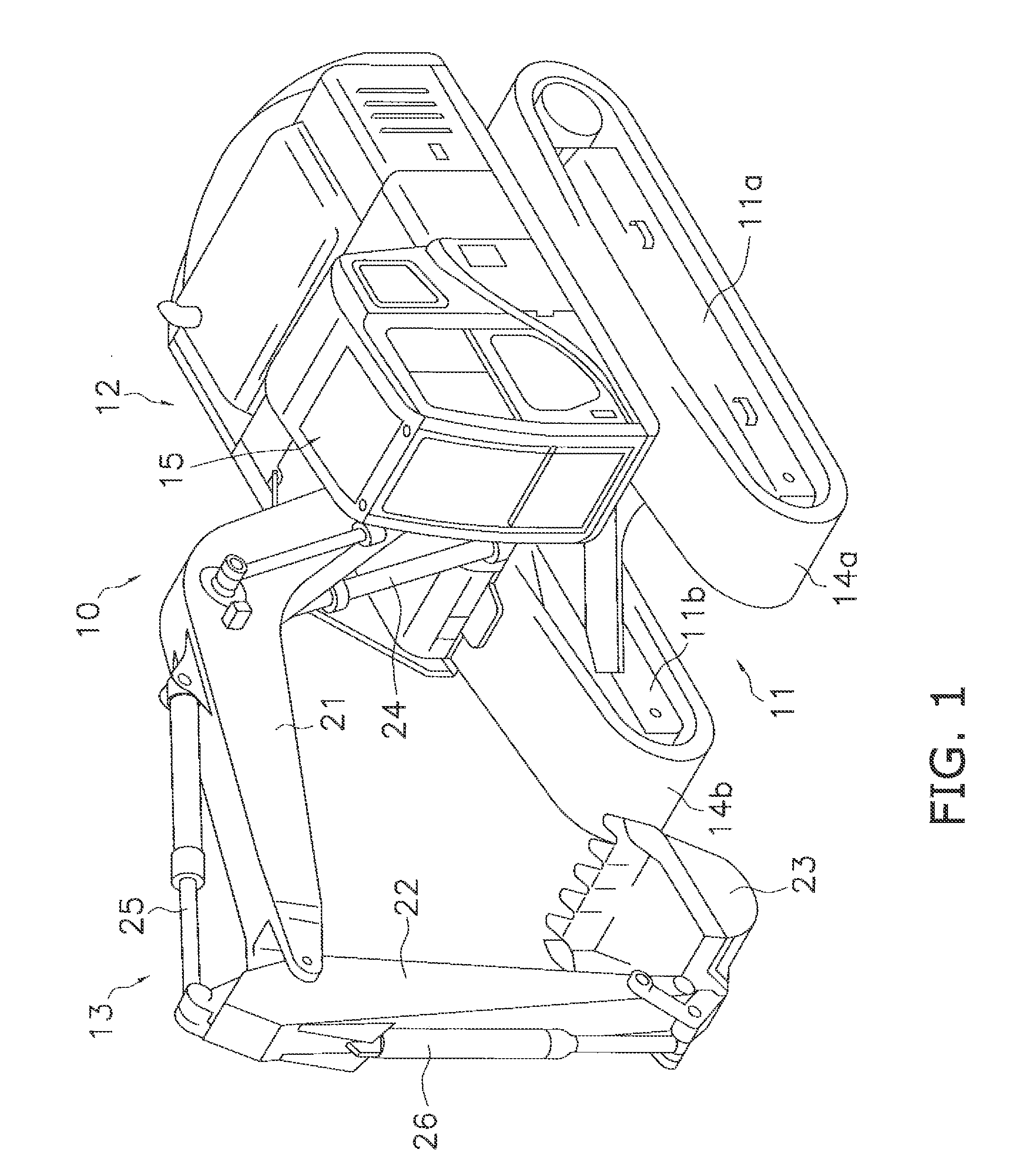
[0027]FIG. 1 illustrates a hydraulic excavator 10 (one example of a work machine) according to an exemplary embodiment of the present invention. The hydraulic excavator 10 includes a travelling unit 11, a revolving unit 12 (one example of a vehicle body) and a working unit 13.

[0028]The travelling unit 11 includes a pair of drive units 11a and 11b. The drive unit 11a includes a track (crawler belt) 14a and a traveling motor (not illustrated in the figures). Likewise, the drive unit 11b includes a track 14b and a traveling motor (not illustrated in the figures). The traveling motors are configured to drive the tracks 14a and 14b for causing the hydraulic excavator 10 to travel.

[0029]The revolving unit 12 is mounted on the travelling unit 11. The revolving unit 12 is configured to revolve on the travelling unit 11 by means of a revolving motor 27 (see FIG. 2). Further, a cab 15 occupies the front left part of the revolving unit 12.

[0030]The working unit 13 is attached...


PUM


Abstract

In a work machine, a control unit controls a pilot control valve for controlling the opening area of a first direction switch valve in executing the combined operation to be less than or equal to that in executing a single operation. The combined operation represents an operation of simultaneously operating first and second actuators. The single operation represents an operation of operating only the first actuator. Further, the control unit determines the opening area of the first direction switch valve in the combined operation based on a hydraulic pressure detected by a hydraulic pressure detector unit.

Description

CROSS-REFERENCE TO RELATED APPLICATIONS[0001]This national phase application claims priority to Japanese Patent Application No. 2009-141436 filed on Jun. 12, 2009. The entire disclosure of Japanese Patent Application No. 2009-141436 is hereby incorporated herein by reference.TECHNICAL FIELD[0002]The present invention relates to a work machine and a control method for work machines.BACKGROUND ART[0003]The work machines such as the hydraulic excavators are embedded with a hydraulic circuit that a hydraulic pump is used in common for driving a plurality of actuators. In such work machines, a large amount of the hydraulic fluid flows towards a less loaded actuator in executing a combined operation of simultaneously driving a plurality of actuators. In this case, shortage of the flow rate of the hydraulic fluid is problematic in a more loaded actuator.[0004]To solve the problem, the well-known work machines have been configured to execute a control of reducing the opening size of the con...

Claims


Application Information

Patent Timeline
IPC IPC(8): E02F9/14F15B13/06
CPCE02F9/2203E02F9/2228E02F9/2282E02F9/2285E02F9/2292E02F9/2296F15B11/162F15B2211/20576F15B2211/3116F15B2211/31582F15B2211/329F15B2211/6355F15B2211/20546E02F9/22F15B11/16F15B11/20
Inventor OHHIGASHI, KOUJINAGATA, NORITAKAUCHIMARU, MASATOSHI
Owner KOMATSU LTD
Why Eureka
Try Eureka